
Branch prediction combining static and dynamic prediction techniques

a dynamic branch prediction and branch prediction technology, applied in the field of pipelined microprocessors, can solve problems such as increased mispredictions, increased mispredictions, and increased mispredictions, and achieve the effects of reducing the probability of collisions with dynamic branch predictors, and reducing the probability of collisions

Inactive Publication Date: 2008-07-22
HEWLETT-PACKARD ENTERPRISE DEV LP
View PDF7 Cites 18 Cited by
  • Summary
  • Abstract
  • Description
  • Claims
  • Application Information

AI Technical Summary

Benefits of technology

[0017]The problems noted above are solved in large part by a computer system having one or more processors. Each processor has a branch predictor which dynamically predicts each conditional branch instruction. Software written for the processors to execute includes static branch prediction instructions embedded in the software. Each branch prediction instruction includes a pair of predictor bits that corresponds to another instruction which may be a conditional br...

Problems solved by technology

Performance suffers on mispredictions and increases on correct predictions.
On the other hand, if the two colliding branches behave differently, they will try to push the shared counter in different directions causing an increased number of mispredictions.
Unfortunately, it has been shown that collisions in dynamic branch predictors are more likely to be destructive than constructive.
First, the number of entries in the predictor table can be increased possibly causing branches that would have collided to index to different entries in the table.
For example, conditional branches that check for error conditions generally result in the take or do not take outcome associated with there not being an error.
While theoretically adequate, Lindsay's approach may not be possible to implement in an existing processor architecture in which the conditional branch instructions have no extra bits in which to encode the dynamic or static prediction choice and, for static prediction, the prediction itself.

Method used


Image

  • Branch prediction combining static and dynamic prediction techniques
  • Branch prediction combining static and dynamic prediction techniques
  • Branch prediction combining static and dynamic prediction techniques

Examples


Embodiment Construction

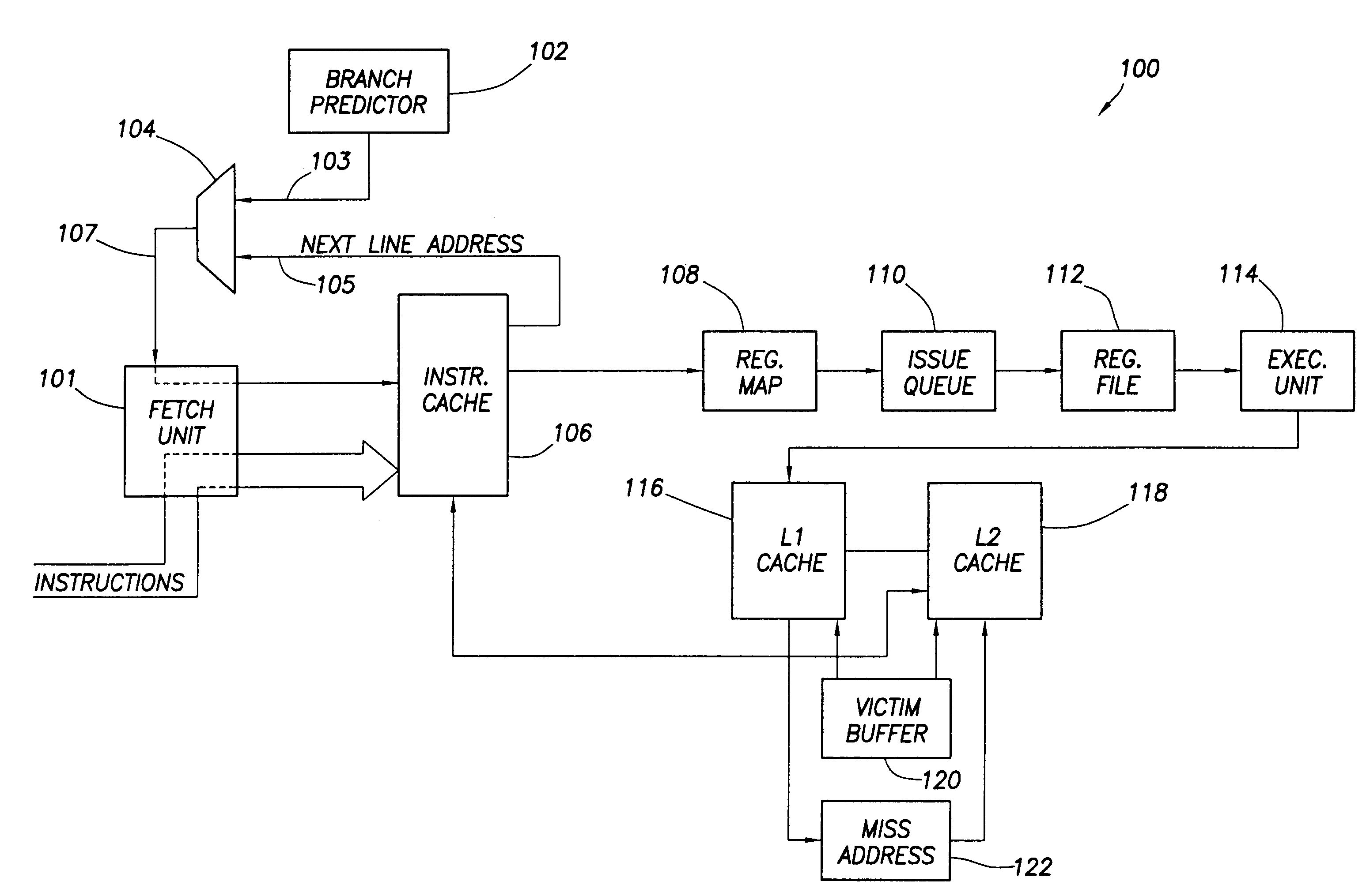
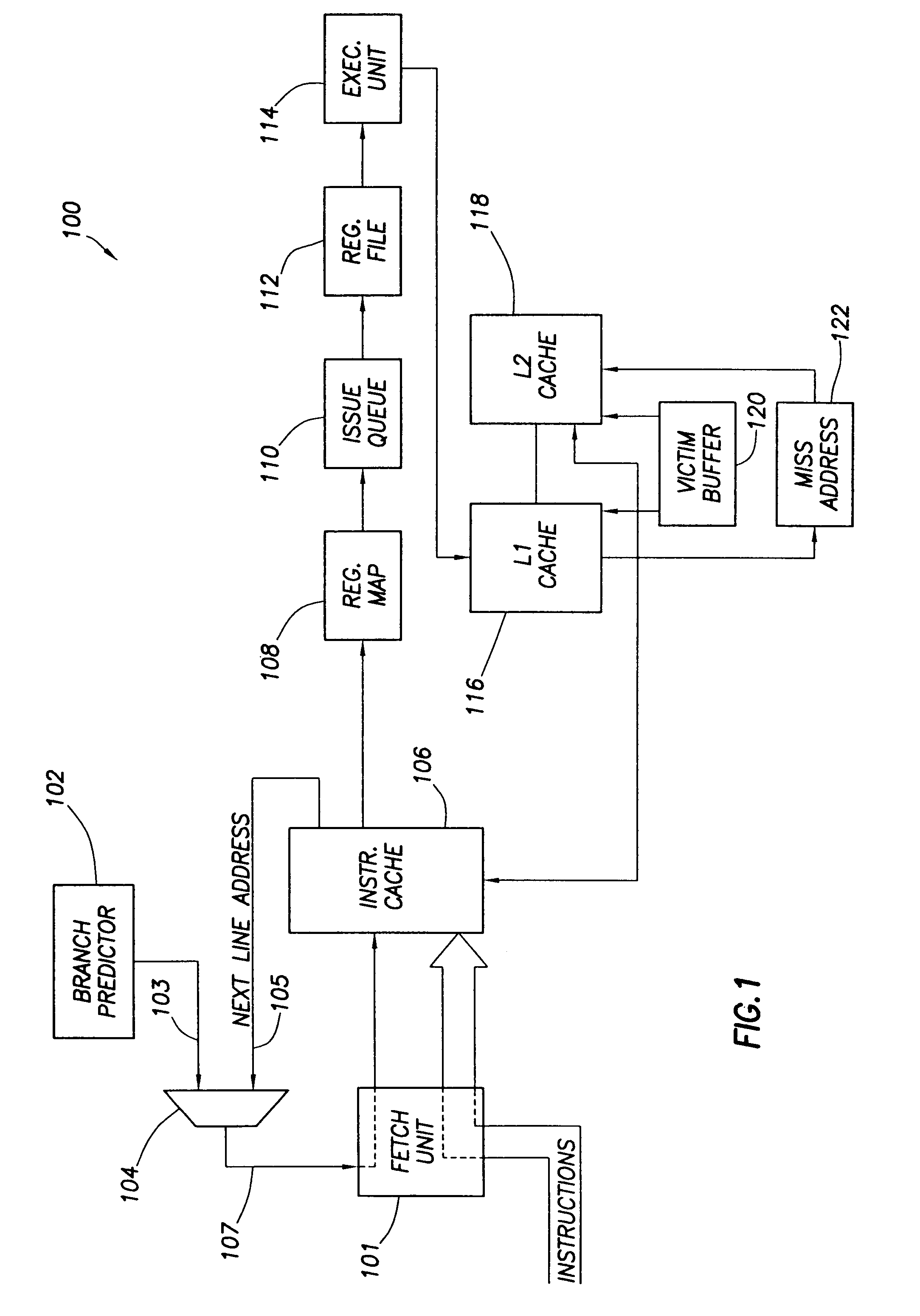
[0023]Referring now to FIG. 1, in accordance with the preferred embodiment of the invention, processor 100 generally comprises a fetch unit 101, a branch predictor 102, a multiplexer 104, an instruction cache 106, a register map 108, an issue queue 110, a register file 112, an execution unit 114, an L1 cache 116, an L2 cache 118, a victim buffer 120 and a miss address file 122. Other components (not specifically shown) or different components can be provided as desired. Further, one or more of the components shown in FIG. 1 can be implemented as a plurality of such components. For example, there may be more than one branch predictor 102, register map 108, issue queue 110, register file 112, execution unit 114, victim buffer 120 and miss address file 122. Additional such components may be provided to permit concurrent processing of multiple instructions through the processor. Further, a set of components 108-114 can be provided to process integer-type instructions and another set to ...


PUM


Abstract

A computer system comprises a processor that comprises a hardware branch predictor and software instructions executed by the processor. The software instructions comprise conditional branch instructions and separate static branch prediction instructions. The static branch prediction instructions comprise a plurality of groups of static branch prediction bits, each group being configurable to provide prediction information for a separate conditional branch instruction.

Description

CROSS-REFERENCE TO RELATED APPLICATIONS[0001]Not applicable.STATEMENT REGARDING FEDERALLY SPONSORED RESEARCH OR DEVELOPMENT[0002]Not applicable.BACKGROUND OF THE INVENTION[0003]1. Field of the Invention[0004]The present invention generally relates to a pipelined, superscalar microprocessor. More particularly, the invention relates to branch prediction in a pipelined microprocessor. Still more particularly, the invention relates to combining static and dynamic branch prediction techniques.[0005]2. Background of the Invention[0006]A microprocessor comprises the logic, typically a semiconductor device, which executes software. Microprocessors thus fetch software instructions from memory and executes them. Each instruction generally undergoes several stages of processing. For example, the instruction must be fetched and decoded to determine the type of instruction (add, multiply, memory write, etc.). Then, the instruction is scheduled, executed and finally retired. Each stage of process...

Claims


Application Information

Patent Timeline
IPC IPC(8): G06F9/00
CPCG06F9/3005G06F9/3848G06F9/3846G06F9/382
Inventor PATIL, HARISH G.EMER, JOEL S.FELIX, STEPHEN
Owner HEWLETT-PACKARD ENTERPRISE DEV LP
Learn More