Vehicle fairing system

a technology for fairings and vehicles, applied in the direction of roofs, transportation and packaging, vehicle arrangements, etc., can solve the problems of increasing fuel consumption, increasing the cost of operation, and causing significant drag, so as to improve the aerodynamic profile of vehicles, reduce the amount of power, and optimize the efficiency of vehicles.

Inactive Publication Date: 2008-07-29
AEROFFICIENT
View PDF30 Cites 115 Cited by
  • Summary
  • Abstract
  • Description
  • Claims
  • Application Information

AI Technical Summary

Benefits of technology

[0010]The invention is a vehicle fairing system for a vehicle having a front vehicular component and a rear vehicular component in tandem and separated by a gap, for optimizing the efficiency of vehicles by improving their aerodynamic profile, and thus reducing the amount of power needed to overcome aerodynamic drag, thereby reducing fuel consumption without affecting loading and unloading operations. The system comprises front end, rear end, and side vehicle fairing structures.
[0011]In one aspect of the invention, the front end vehicle fairing structure comprises a top surface adapted to be attached to the front end of the roof of the rear vehicular component (sometimes referred to herein as the “horizontal surface”) and two side surfaces each adapted to be attached to respective sides of the rear vehicular component and joining opposite ends of the top surface and generally perpendicular to the top surface. Each of the horizontal and vertical surfaces has a proximal edge adapted to be positioned adjacent a vehicle, and a distal edge adapted to be positioned away from the vehicle with respect to the respective proximal edge. The area bounded by the distal edges of the surfaces is smaller than an area bounded by the proximal edges. The fairing structure is positioned adjacent a rear vehicular component (in preferred embodiments, the front of a trailer box) in a gap between said rear vehicular component and a front vehicular component (such as a tractor cab), sufficiently close to the front vehicular component to impede or otherwise lessen transverse and vertical airflow in the gap, lessening aerodynamic drag. This is accomplished by positioning the distal and proximal edges of the surfaces relative to each other such that the fairing structure, when positioned adjacent the rear vehicular component in the gap, re-directs air from the rear vehicular component and additionally impedes or otherwise lessens air flow in the gap, forming an effective closure of the gap.

Problems solved by technology

The amount of power needed to move a vehicle over land or through the air increases with the speed of the vehicle due to aerodynamic drag.
The amount of power necessary to overcome aerodynamic drag directly translates into increased fuel consumption, and thus cost of operation.
While this fairing structure significantly reduces drag at the rear end of the trailer box a significant amount of drag is also associated with the front of the trailer box, where there is known to be an area of high pressure and relatively stagnant air approximately at the middle of the forward vertical face of the trailer cab.
U.S. Pat. No. 4,746,160 discloses a semi-trailer truck with front air flow panels and fabric side skirts, but does not address the problem of drag at the rear end of the trailer box.
Similarly, U.S. Pat. No. 4,611,847 discloses inflatable / extendable skirts along the side of a tractor-trailer to reduce air drag, but does not address the problem of drag at the top or rear ends of the vehicle.

Method used


Image

  • Vehicle fairing system
  • Vehicle fairing system
  • Vehicle fairing system

Examples


Embodiment Construction

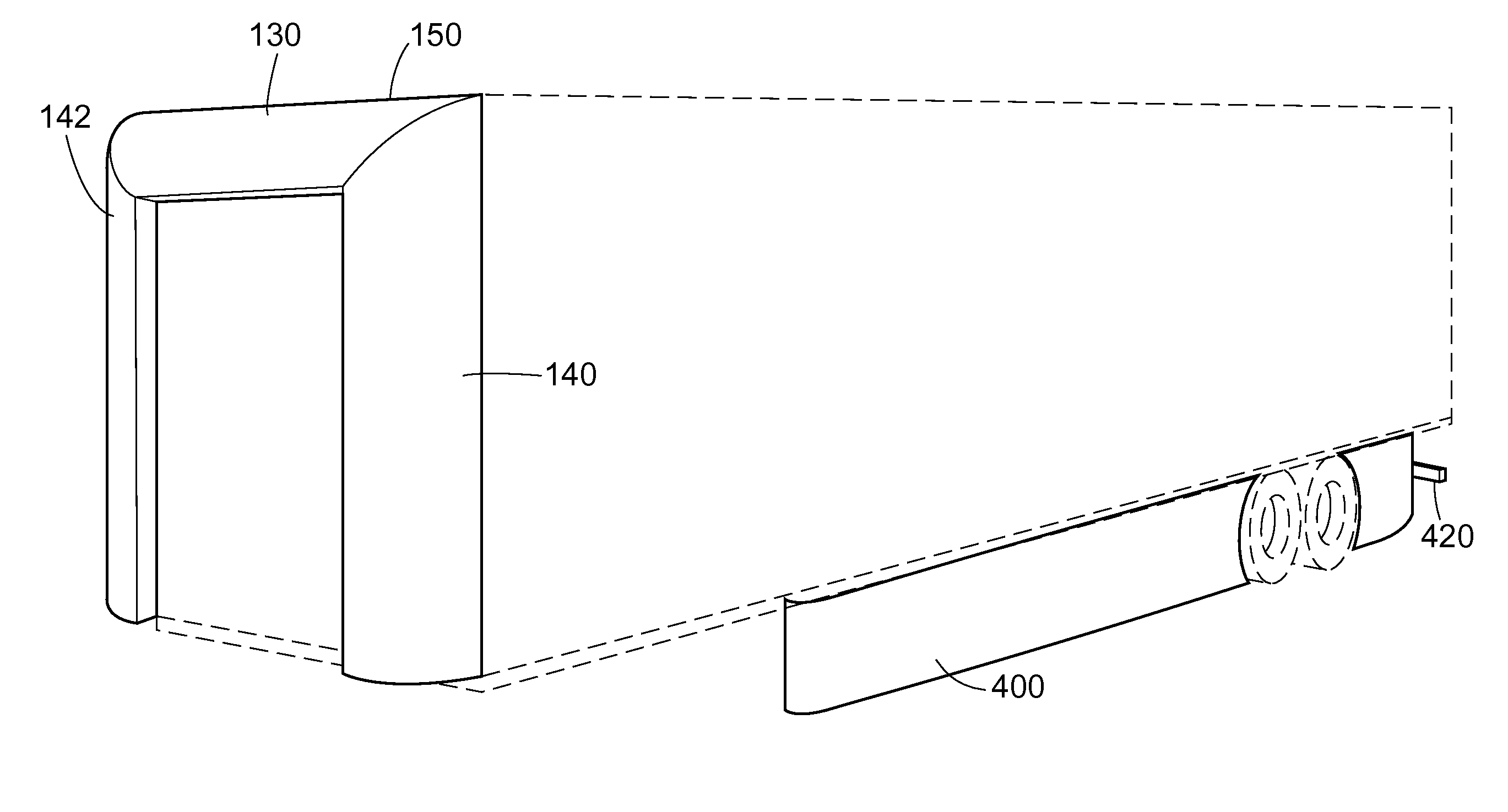
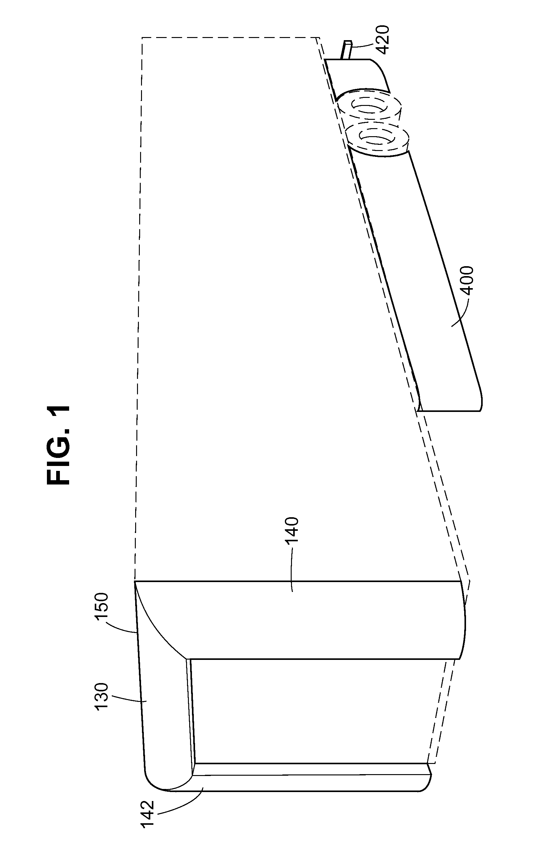
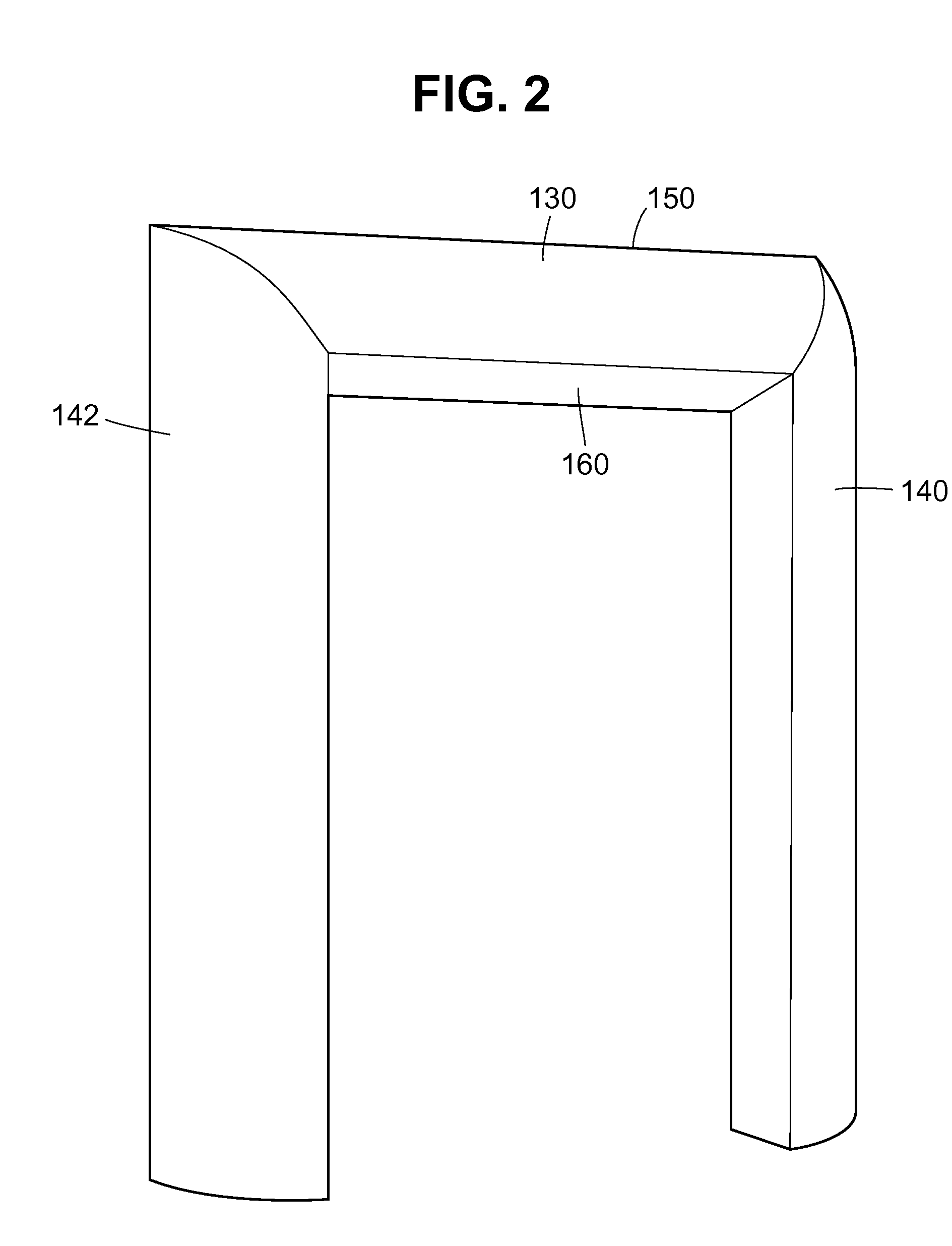
[0021]It is believed that the vehicle fairing system disclosed herein significantly increases the efficiency of vehicles, particularly tractor-trailers, by improving their aerodynamic profile, and thus reducing aerodynamic drag, without affecting loading and unloading operations.

[0022]The large rectangular ends of typical trailer boxes create an area of reduced pressure behind the trailer box as it moves over the highway. In addition, in such tandem vehicle arrangements, the rear vehicular component often projects above the front vehicular component and thus causes additional aerodynamic drag of a type referred to as form drag. Also, in such tandem vehicle arrangements, the rear vehicular component is separated from the front vehicular component by a gap, which also creates aerodynamic drag. All of these phenomena increase wind resistance, and thus decrease the efficiency of the vehicle. Still further, air currents are produced underneath a moving tractor-trailer, which also increas...


PUM


Abstract

A combination of vehicle fairing structures forming a fairing system having a front end structure, a rear end structure, and first and second side structures, for optimizing the aerodynamic profile of vehicles, especially tractor-trailer combinations.

Description

[0001]This application claims the benefit of priority U.S. Provisional Application No. 60 / 844,442 and U.S. Provisional Application No. 60 / 844,511, each filed Sep. 13, 2006, and which are each incorporated by reference herein.BACKGROUND OF THE INVENTION[0002]1. Field of the Invention[0003]This invention relates to a system for improving the aerodynamic profile of vehicles utilizing front end, rear end and side vehicle fairing structures, especially for use on a tractor-trailer. The system improves fuel consumption without affecting loading and unloading operations.[0004]2. Description of Related Art[0005]The amount of power needed to move a vehicle over land or through the air increases with the speed of the vehicle due to aerodynamic drag. The amount of power necessary to overcome aerodynamic drag directly translates into increased fuel consumption, and thus cost of operation.[0006]A variety of innovations aimed at reducing the aerodynamic drag of various transport vehicles, includi...

Claims


Application Information

Patent Timeline
Patent Type & Authority Patents(United States)
IPC IPC(8): B60R27/00B60R99/00
CPCB62D35/001
Inventor REIMAN, JAMESHEPPEL, PETER
Owner AEROFFICIENT
Why Eureka
Try Eureka