Liquid container

a liquid container and liquid technology, applied in printing, other printing apparatus, etc., can solve the problems of difficult to detect the amount of ink, low detection accuracy at the ink end, and printing becomes impossibl

Inactive Publication Date: 2008-07-29
SEIKO EPSON CORP
View PDF49 Cites 43 Cited by
  • Summary
  • Abstract
  • Description
  • Claims
  • Application Information

AI Technical Summary

Benefits of technology

[0113]Besides, preferably, there is further included a press mechanism for pressing the flexible film toward a direction of decreasing the volume of the second liquid reservoir chamber, and magnitude of pressure applied to the flexible film by the press mechanism is set to such a value that the second liquid reservoir chamber can be expanded when the pressure of the pressurized fluid is transmitted through the liquid to the liquid in the inside of the second liquid reservoir chamber.
[0114]Besides, preferably, at least a part of the container body is constituted by a member having rigidity, and the second liquid reservoir chamber is formed by sealing an opening of a recess formed in the member having the rigidity with the flexible film.
[0115]Besides, preferably, the narrow flow path includes a small hole formed in a bottom of the recess.

Problems solved by technology

Thus, for example, even in the case where the mounting of the ink cartridge to the ink-jet printer is poor, and the ink is not actually supplied to the inkjet printer although the pressurizing pump is operated, as long as the operation of the pressurizing pump is detected by the pressure sensor, it is mistaken that the ink is being supplied.
In the ink cartridges provided with the function of detecting the amount of remaining ink, the former can continuously detect the variation in the amount of ink in relation to detecting the thickness of the ink bag, but has a problem of low detection accuracy at ink end.
However, the latter is difficult to detect the amount of ink before the remaining ink amount reaches a set amount, such as ink end, because it detects the pressure of ink in the ink channel.
Further, the latter suffers from a problem that the amount of ink for printing is significantly small after ink end is detected and thus printing becomes impossible.
In a conventional ink cartridge in which compressed air is introduced into the inside of a container and ink is delivered to the outside of the container by its pressure, an assembling operation for forming a sealing structure between a pressurizing chamber into which the compressed air is introduced and a reservoir chamber in which the ink is stored or a disassembling operation has been complicated.
Besides, in the conventional ink cartridge of the foregoing type, even if an attempt is made to recycle a part of the components after use, it is structurally difficult to remove only necessary components, and the recycling has been very difficult or impossible.
Further, in the conventional ink cartridge of the foregoing type, there has been a problem that the compressed air introduced into the inside of the ink cartridge permeates through a flexible film separating the ink from the compressed air and dissolves in the ink, and the print quality is lowered.
However, in the conventional ink cartridge using the electric contact, there is a case where the electric contact causes poor contact due to the poor mounting of the ink cartridge to the ink-jet recording apparatus or the attachment of a foreign matter to the electric contact.
When the poor contact occurs at the electric contact as stated above, the output of the detection unit of the remaining amount of ink is not transmitted to the ink-jet recording apparatus side, or the operation of the detection unit becomes impossible since the supply of electric power to the detection unit can not be performed, and there has been possibility that the detection of the remaining amount of ink becomes impossible, and poor printing is caused
However, since a mounting space of the detection unit and the communication unit in the inside of the liquid container is limited, it is desired that while the space efficiency is considered, the detection unit and the communication unit are incorporated in the inside of the liquid container, and electrical connection of both is achieved without fail.
However, the valve unit in the liquid container has a problem that when the valve body is pressed from the outside in a state where the liquid container is not mounted in the liquid consuming apparatus, air flows into the inside of the liquid container, or the liquid in the inside of the liquid container leaks to the outside.
However, there is a problem that this measure increases the number of parts, and the layout of part arrangement becomes difficult.
Further, even if the check valve is provided as the air inflow preventing measure, the problem of the leakage of the liquid from the liquid container by pressing the valve body from the outside is not resolved.

Method used


Image

  • Liquid container
  • Liquid container
  • Liquid container

Examples


first embodiment

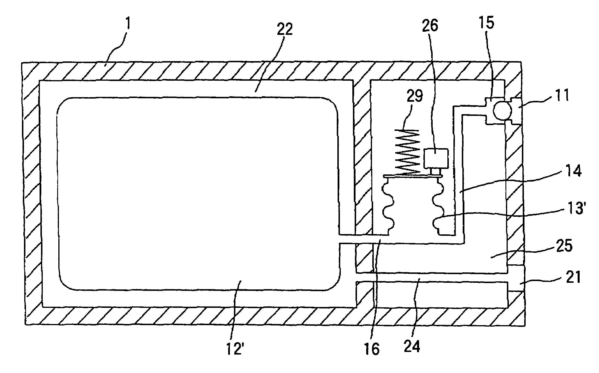
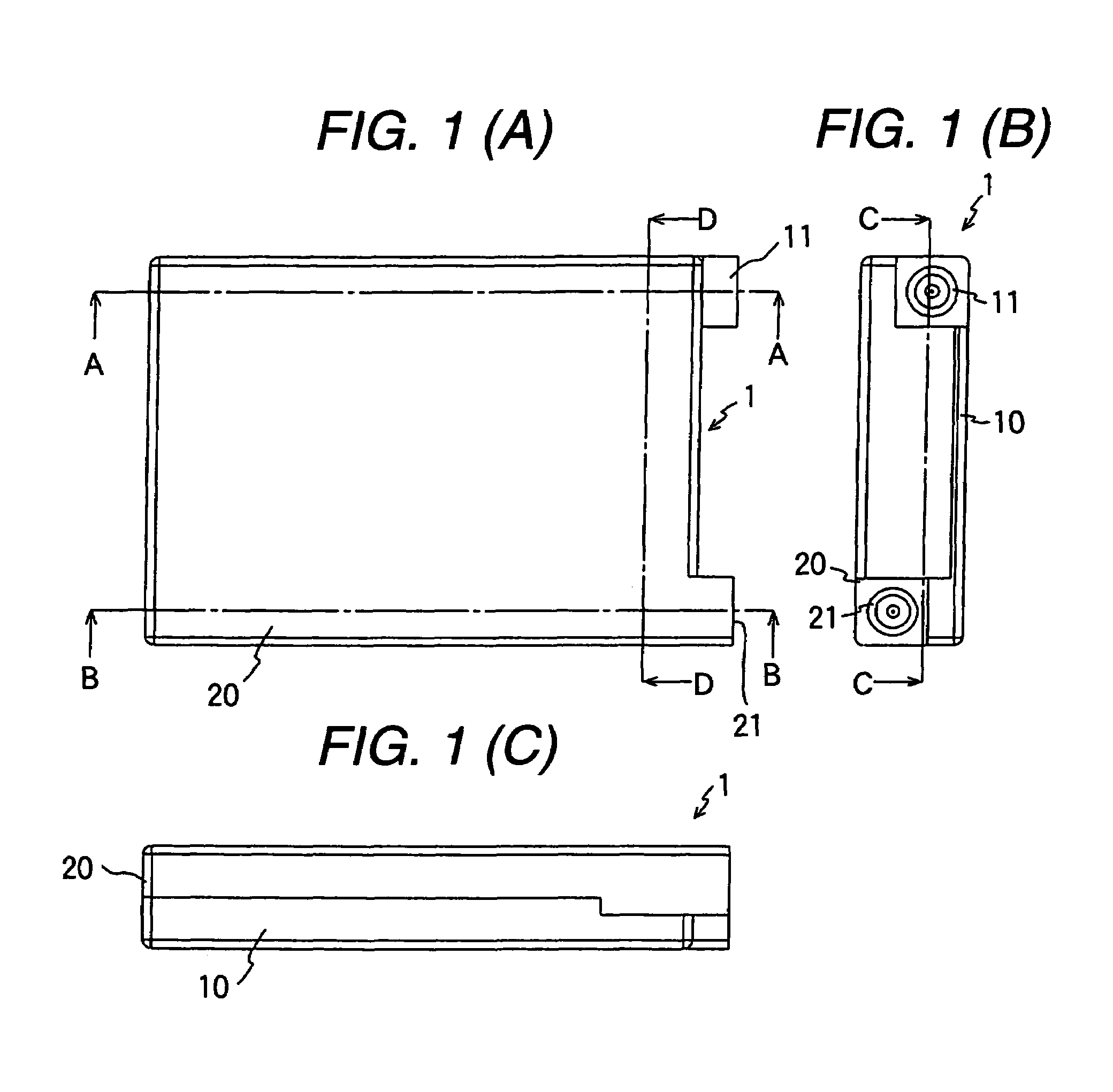
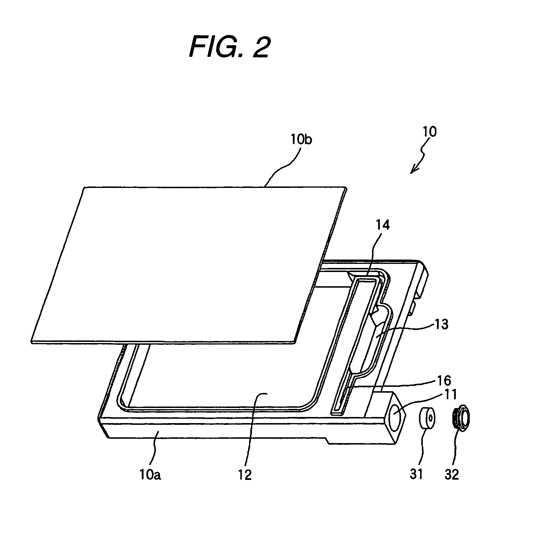
[0202]FIGS. 1A to 1C are schematic diagrams illustrating, as one embodiment of a liquid container of the invention, an ink cartridge for containing ink to be fed to a recording apparatus as a liquid consuming apparatus. In the embodiment, closed-bottom boxes (case members) 10 and 20 are combined to form a hard case constructing a cartridge 1 as a liquid container. The boxes 10 and 20 are half shells of the hard case, which are in almost symmetry to each other.

In the surface on the tip end side in the mounting direction (FIG. 1B), there are formed an ink delivery port 11 and an air introduction port 21. The ink delivery port 21 serving as a liquid delivery port, is connectable to an ink supplying needle communicating with a recording head of a liquid consuming apparatus, which is the recording device in the embodiment. An air introduction port 21 serving as a pressurized fluid introduction port is connectable to an air supplying needle communicating with a pressurized fluid source.

[0...

second embodiment

[0232]Hereinafter, as a second embodiment of a liquid container of the invention, an ink cartridge for an ink-jet recording apparatus will be described with reference to the drawings.

[0233]FIGS. 18 and 19 are views showing the outer appearance of an ink cartridge 101 according to this embodiment, FIGS. 20 and 21 are exploded perspective views of the ink cartridge 101, and FIG. 22 is sectional view of the ink cartridge 101 and its exploded view.

[0234]The ink cartridge 101 includes a container body 102, and this container body 102 is constituted by a first case member 102A, a second case member 102B and a third case member 102C. As is understood from FIGS. 20 and 21, plural heat caulking ribs 103 are formed at a peripheral part of the second case member 102B, and these heat caulking ribs 103 are inserted in plural through holes 104 and 105 formed in the first case member 102A and the third case member 102C, and are subjected to heat caulking. By this, the first case member 102A is hel...

third embodiment

[0370]A third embodiment of the invention will be described with reference to FIGS. 39 to 46. In the third embodiment, the sensor chamber through hole 112 of the second embodiment is formed as a sensor chamber recess 212. Members of the third embodiment corresponding to members described in the second embodiment are denoted by the same reference numerals as those of the second embodiment, and their duplicate description will be omitted.

[0371]An ink injection port 108 formed in a first case member 102A communicates with an ink chamber through hole 111 through an ink injection flow path 132. Besides, the ink chamber through hole 111 and the sensor chamber recess 212 are communicated with each other through a narrow communicating path 135A. Further, a filter mounting part 131 in which a filter 130 is inserted and the sensor chamber recess 212 are communicated with each other through a narrow communicating path 135B.

[0372]Then, in an ink cartridge 101 according to this embodiment, as sh...


PUM


Abstract

The invention provides a liquid container for storing liquid to be supplied to a liquid consuming apparatus. The liquid container is constructed such that pressurized fluid is sent to its inside so that the liquid in the inside is delivered to the outside. The liquid container includes a container body which stores the liquid in its inside. The container body includes a pressurized fluid introduction port for introducing the pressurized fluid to the inside and a liquid delivery port for delivering the liquid to the outside. A detection unit is provided in the container body and outputs an output signal which is changed in accordance with a change in pressure of the liquid in the inside of the container body.

Description

BACKGROUND OF THE INVENTION[0001]The present invention relates to a liquid container for storing liquid to be supplied to a liquid consuming apparatus such as an ink-jet recording apparatus.[0002]As a typical example of a conventional liquid consuming apparatus, there is a liquid ejecting apparatus which ejects a liquid droplet from an ejecting head, and as a typical example of the liquid ejecting apparatus, there is an ink-jet recording apparatus provided with an ink-jet recording head for image recording. Other liquid ejecting apparatuses include, for example, an apparatus provided with a color material ejecting head used for manufacture of a color filter of a liquid crystal display or the like, an apparatus provided with an electrode material (conductive paste) ejecting head used for electrode formation of an organic EL display, a surface emitting display (FED) or the like, an apparatus provided with a biological organic material ejecting head used for manufacture of a biochip, a...

Claims


Application Information

Patent Timeline
Patent Type & Authority Patents(United States)
IPC IPC(8): B41J2/175
CPCB41J2/17513B41J2/17523B41J2/17566B41J2/17553B41J2/17556B41J2/17546B41J2/17503
Inventor NAKA, TAKAHIROKATAKURA, TAKAHIROKOBAYASHI, ATSUSHISHINADA, SATOSHIKUMAGAI, TOSHIOISHIZAWA, TAKUSEINO, TAKEOMIYAZAWA, HISASHIFUKANO, TAKAKAZUKIMURA, HITOTOSHIUEHARA, YASUNAOMATSUYAMA, MASAHIDE
Owner SEIKO EPSON CORP
Why Eureka
Try Eureka