Temporary road element

a technology of temporary roads and components, applied in the field of roadways, can solve the problems of extreme conditions of roads, roads that cannot be driven across scraped or unprepared ground surfaces, roads that cannot be driven across extremely rugged and uneven terrain, etc., and achieve the effect of stable, secure and long-lasting

Active Publication Date: 2008-07-29
CHAMPAGNE EDITION
View PDF14 Cites 59 Cited by
  • Summary
  • Abstract
  • Description
  • Claims
  • Application Information

AI Technical Summary

Benefits of technology

[0014]It is a main objective of the present invention to provide a road mat element that is stable, secure and long lasting.
[0015]It is another objective of the present invention to provide a road mat element that if flexible to allow the mat to properly conform to any supporting surface on which it is placed, even if extremely heavy traffic will traverse the element.
[0016]It is another objective of the present invention to provide a road mat element that is extremely durable.

Problems solved by technology

Often these roads are located in areas that are subject to extreme temperature ranges and must be left unattended for great lengths of time.
Accordingly, these roads are subject to extreme conditions.
The axle loading of a typical heavy equipment truck is such that it is not feasible to drive it across a scraped or unprepared ground surface without experiencing sinking, jamming of the truck, and similar impediments.
However, the nature of the industries causes the roads to traverse extremely rugged and uneven terrain.
Exacerbating the problem is the fact that many of the roads, once constructed, will remain unattended and unrepaired for great lengths of time.
Heretofore known roads have been deficient in balancing these competing objectives and the constraints placed on the roads.
Furthermore, there are frequently regulations associated with performing work in environmentally sensitive areas, which require the site to be returned to its original pristine condition when work is completed.
Such site restoration can become quite expensive and labor intensive.
Construction of a temporary road bed using individual boards is costly and labor intensive.
The heavy equipment that travels over the road bed often damages a large number of the boards so that the boards cannot be reused.
Disassembly of the road bed is also labor intensive and damages many of the boards not previously damaged during use.
Still further roads formed of wood are subject to degrading, separation and the like.
If nails are used to connect boards, these nails can become dislodged and may damage the tires of vehicles traversing the road.
If the nails become dislodged, the boards can become separated which can damage the tires of vehicles traversing the road or even producing slick spots.
Still further, if the wood becomes damaged or nails fall out, elements of the road may remain after the road is removed thereby causing undesirable environmental damage.
If the boards become separated, vehicles may cause damage to the ground in the open areas, again causing undesired environmental damage.
Therefore, temporary roadways formed of wood have many undesirable characteristics.
However, the prior methods of constructing a temporary road bed are generally expensive and time consuming.
Although the preconstructed mats can reduce the time for constructing a temporary road, the cost of manufacturing the mats and the difficulty of moving and assembling the mats have limited their use.
These steps in the prior methods are expensive and time consuming.
Other known methods are also time consuming and labor intensive.
Still further, these known methods do not produce a mat that is stable and which has a good memory so it will return to its initial condition after supporting a very heavy load, even a load as high as thousands of tons which is common in the construction and oil drilling industry and even if the road is located in an area that is subject to extreme environmental conditions and which may be left unattended for great lengths of time.
Heretofore known mats are quite likely to become damaged and permanently distorted by such heavy loads and conditions.
A damaged or distorted mat must be replaced, which can add expense to the overall job through the cost of materials as well as the cost of labor, which is doubled because the damaged or distorted mat must be removed and then replaced.
An unreplaced damaged road may create a hazard to vehicles and to the environment.

Method used


Image

  • Temporary road element
  • Temporary road element
  • Temporary road element

Examples


Embodiment Construction

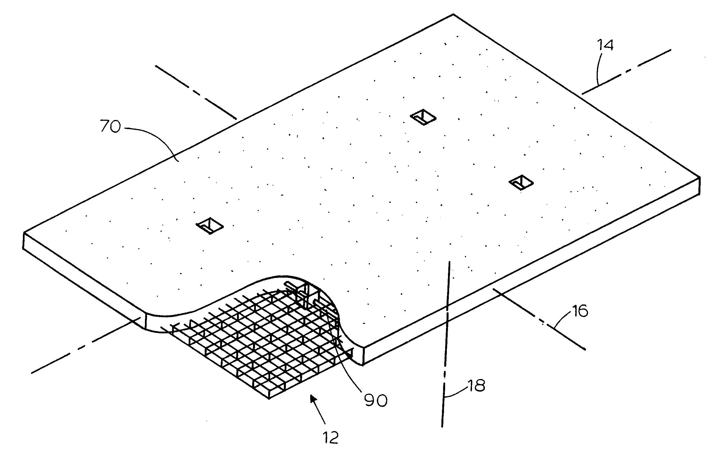
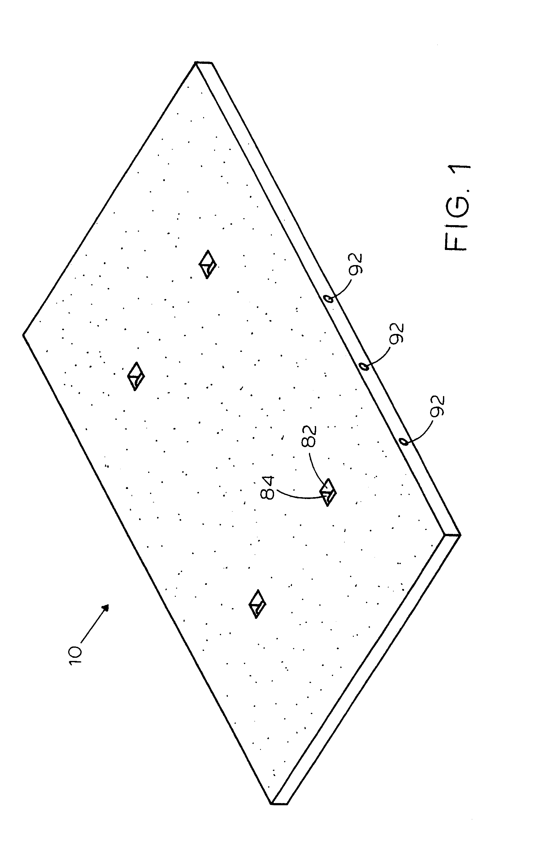
[0030]Referring to the figures, it can be understood that the present invention is embodied in a temporary road element 10 that achieves the above-stated objectives.

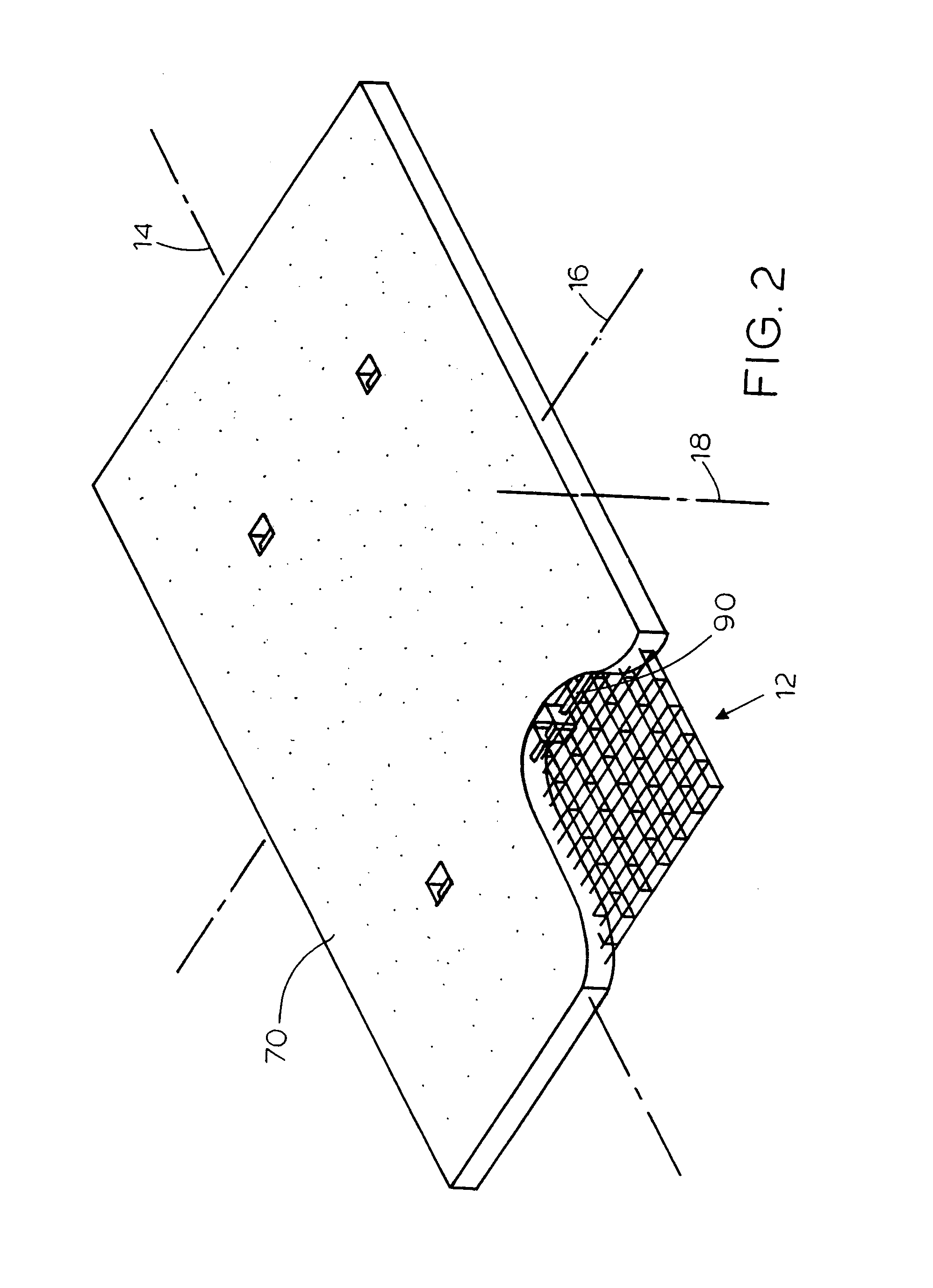
[0031]Element 10 comprises a one-piece cage 12. Cage 12 is described herein as being “one-piece” in that it is monolithic and is formed to be a one-piece element as opposed to a plurality of connected parts. Being one-piece, cage 12 has excellent strength characteristics which can withstand thousands of tons of load without permanently deforming, has good temperature resistance even when subjected to extreme temperature conditions, such as might occur in the arctic or the like, yet is flexible enough to conform to extremely uneven terrain in a manner that will properly support heavy vehicular traffic. The one-piece feature of mat 10 also makes that mat durable so that it can be left unattended for great lengths of time.

[0032]One-piece cage 12 is best shown in FIGS. 2-4 and includes a longitudinal axis 14, a transverse ax...


PUM

PropertyMeasurementUnit
flexibleaaaaaaaaaa
pressureaaaaaaaaaa
thicknessaaaaaaaaaa

Abstract

A road element is formed of a one-piece cage that includes two layers of orthogonally arranged rebars which are welded together. The layers are connected by connecting rebars that are welded to the rebars of the layers at the intersections and the one-piece cage is encased in a flexible material formed of crumb rubber, urethane, and fibers from land vehicle tires. Plates can be included with the one-piece cage to further enhance the strength of the element.

Description

TECHNICAL FIELD OF THE INVENTION[0001]The present invention relates to the general art of roads and roadways, and to the particular field of load-supporting surfaces used as a temporary road or temporary road bed.BACKGROUND OF THE INVENTION[0002]Many work sites, such as construction sites, mining sites, farming, logging, gas and oil drilling sites, as well as others, often occur in areas where there is no prepared road bed. It is customary in the oilfield industry to have the requirement of transporting heavy machinery on trucks to remote areas in fields and the like where there is no prepared roadbed. Such areas may be on soft ground, mud, swam, wetlands, tundra, muskeg, sand, or the like. Often these roads are located in areas that are subject to extreme temperature ranges and must be left unattended for great lengths of time. Accordingly, these roads are subject to extreme conditions.[0003]The axle loading of a typical heavy equipment truck is such that it is not feasible to driv...

Claims


Application Information

Patent Timeline
Patent Type & Authority Patents(United States)
IPC IPC(8): E01C9/08E01C5/18E01C5/22
CPCE01C5/18E01C9/086E01C5/20
Inventor LUKASIK, MARCKCHAMPAGNE, ALANBREAULT, MARC POUL JOSEPHBREAULT, ANDRE OCTAVE JOSEPH
Owner CHAMPAGNE EDITION
Why Eureka
Try Eureka