Switching power supply unit and voltage converting method

a technology of switching power supply and voltage conversion, which is applied in the direction of ignition automatic control, conversion with reversal, instruments, etc., can solve the problems of low reverse withstand voltage of diodes with small forward voltage drop

Inactive Publication Date: 2008-07-29
TDK CORPARATION
View PDF15 Cites 13 Cited by
  • Summary
  • Abstract
  • Description
  • Claims
  • Application Information

AI Technical Summary

Benefits of technology

[0009]The predetermined voltage, that is, the maximum value (peak value) of the surge voltage to be suppressed is 4×Vin / n (where Vin denotes direct current input voltage, and n denotes the ratio between the primary-side winding and the secondary-side winding of the power converting transformer) as described in the paragraphs [0062] to [0065] of the above-mentioned publication. The value is used in the case where the rectifier circuit is of a center tap type. In the case where the rectifier circuit is of a full bridge type, based on the circuit configuration, the predetermined voltage is the half of the value, that is, 2×Vin / n. Although the snubber circuit of Japanese Patent Publication No. 3,400,443 can suppress the surge voltage to a certain degree, there is room for improving the maximum value.
[0010]In view of the drawback of the invention, it is desirable to provide a switching power supply unit and a voltage converting method capable of suppressing a surge voltage applied to an output rectifier device more effectively.
[0013]In the first switching power supply unit as an embodiment of the invention, preferably, the second bridge circuit further includes third switching elements each of which is connected in parallel with each of the pair of second capacitative elements, the turn ratio between a primary winding and a secondary winding of the first transformer is different from the turn ratio between a primary winding and a secondary winding of the second transformer, and the driving circuit selectively operates the first or second bridge circuits in accordance with magnitude of the DC input voltage. With the configuration, the second bridge circuit can also perform switching operation, and a DC output voltage can be supplied at a voltage conversion ratio different from that in the case of performing switching operation by the first bridge circuit. Therefore, by selectively operating the first and second bridge circuits in accordance with magnitude of an input voltage, the range of the input voltage based on which a target output voltage can be supplied is widened. In this case, the third switching element may be a field effect transistor, and the second capacitative element may be formed of parasitic capacitance of the field effect transistor. With the configuration, the number of devices used is reduced and the circuit configuration is simplified.
[0014]In the first switching power supply unit as an embodiment of the invention, preferably, the second bridge circuit further comprises a second rectifier element connected in a reversed polarity and in parallel with at least one of the pair of second capacitative elements in an opposite direction. With such a configuration, ringing operation when the surge voltage is generated is suppressed. In this case, the second bridge circuit may include a field effect transistor connected in parallel with the second capacitative element, the second rectifier element may be formed of a parasitic diode of the field effect transistor, and the second capacitative element may be formed of parasitic capacitance of the field effect transistor. With such a configuration, the number of devices used is reduced and the circuit configuration is simplified.
[0035]In the switching power supply unit and the voltage converting method as an embodiment of the invention, the energy in the direction of suppressing the surge voltage applied to the rectifier elements is injected into the rectifier circuit. Consequently, the reverse voltage applied to the rectifier elements can be made lower than a voltage to be inherently applied for a certain period, and rise in the surge voltage can be suppressed more effectively.

Problems solved by technology

However, the diode having a small forward voltage drop has also a low reverse withstand voltage.

Method used


Image

  • Switching power supply unit and voltage converting method
  • Switching power supply unit and voltage converting method
  • Switching power supply unit and voltage converting method

Examples


first embodiment

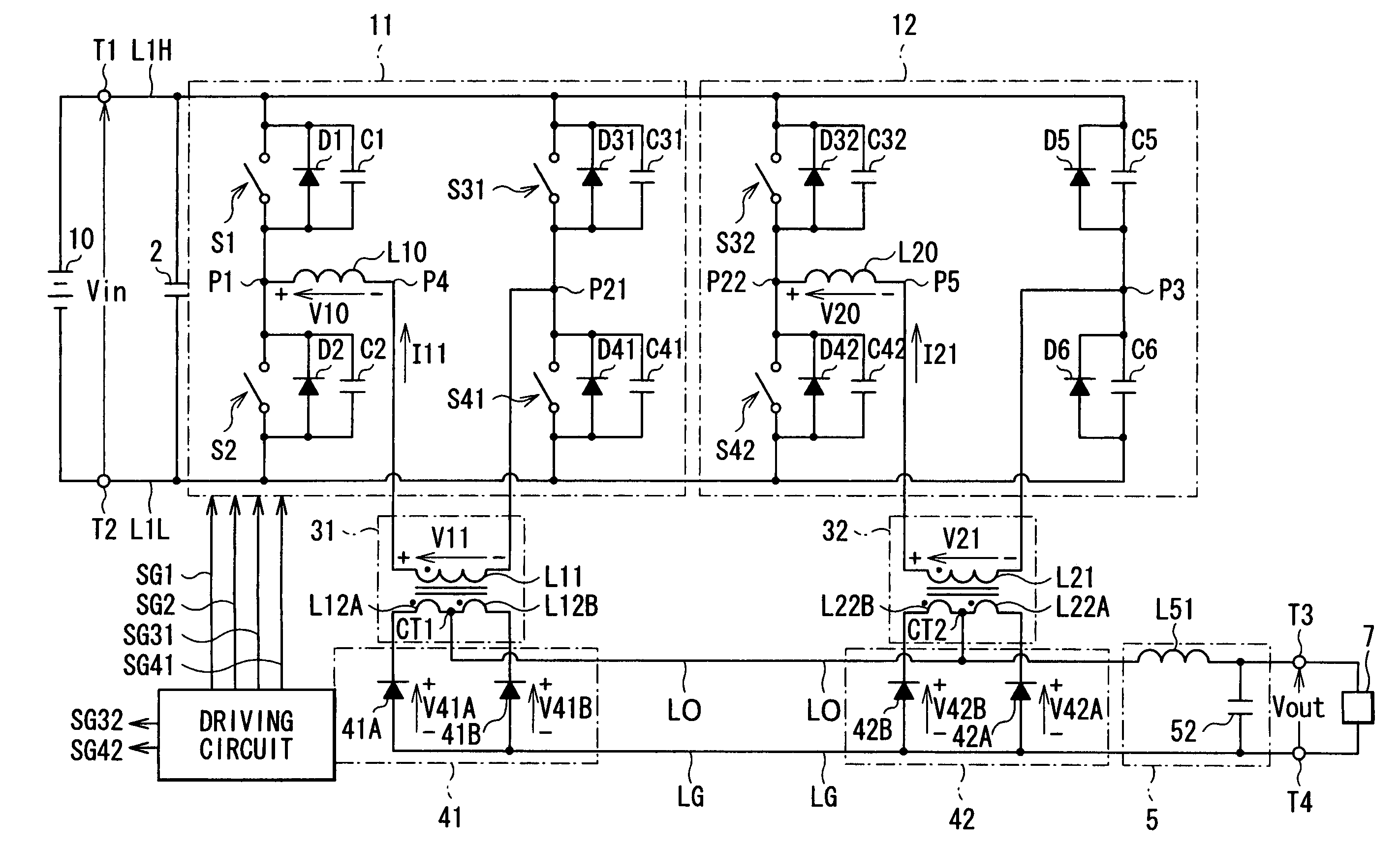
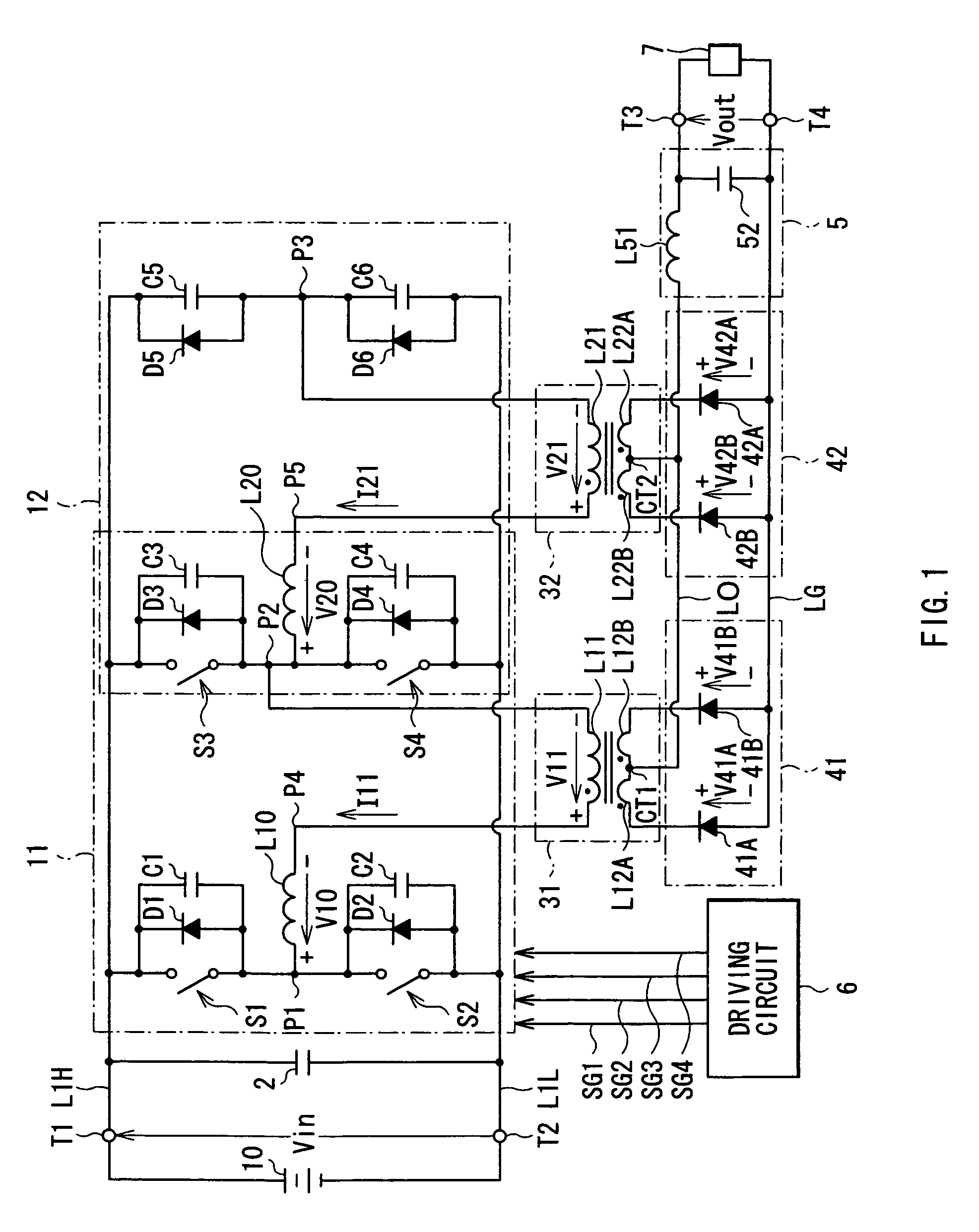
[0056]FIG. 1 shows a configuration of a switching power supply unit according to a first embodiment of the invention. The switching power supply unit functions as a DC-DC converter for converting a high DC input voltage Vin supplied from a high-voltage battery 10 to a lower DC output voltage Vout, and supplying the DC output voltage Vout to a not-shown low-voltage battery to drive a load 7. Since a voltage converting method according to the first embodiment is embodied by the switching power supply unit according to the embodiment, it will be also described below.

[0057]The switching power supply unit has a first bridge circuit 11, a second bridge circuit 12 and an input smoothing capacitor 2 provided between a primary-side-high-voltage line L1H and a primary-side-low-voltage line L1L, an inductor L10 for resonance connected to the first bridge circuit 11 so as to form an H bridge, an inductor L20 for resonance connected to the second bridge circuit 12 so as to form an H bridge, a tr...

second embodiment

[0110]A second embodiment of the invention will now be described.

[0111]In the first embodiment, the switching power supply unit in which the bridge circuits 11 and 12 are partially made common has been described. In the second embodiment, a switching power supply unit in which the bridge circuits 11 and 12 are constructed independently of each other will be described.

[0112]FIG. 13 shows the configuration of the switching power supply unit according to the second embodiment. In FIG. 13, the same reference numerals are designated to the same components as those shown in FIG. 1 and their description will not be repeated. The switching power supply unit has two bridge circuits (the first and second bridge circuits 11 and 12) which are independent of each other. The configuration of the other part is similar to that in the case of FIG. 1.

[0113]Concretely, the first bridge circuit 11 has four switching elements S1, S2, S31, and S41 and capacitors C1, C2, C31, and C41 and diodes D1, D2, D3...

third embodiment

[0119]A third embodiment of the present invention will now be described.

[0120]Although the switching power supply unit having the configuration in which the shift-side switching elements (the switching elements S31, S41, S32, and S42 shown in FIG. 13) in the bridge circuits 11 and 12 are commonly used has been described in the first embodiment, in the third embodiment, a switching power supply unit having a configuration in which fixed-side switching elements in the bridge circuits 11 and 12 are commonly used will be described.

[0121]FIG. 14 shows the configuration of the switching power supply unit according to the third embodiment. In the diagram, the same reference numerals are designated to the same components as those shown in FIG. 1 and their description will not be repeated. As described above, the switching power supply unit includes the bridge circuits 11 and 12 having a configuration in which the fixed-side switching elements (the switching elements S3 and S4) in the bridge...


PUM


Abstract

The present invention provides a switching power supply unit and a voltage converting method capable of suppressing a surge voltage applied to an output rectifier element more effectively. Energy in the direction of suppressing reverse voltages (surge voltages) applied to a plurality of rectifier diodes is injected into a rectifier circuit. Reverse voltages applied to the plurality of rectifier diodes are maintained to be lower than a voltage to be inherently applied for a predetermined period. Therefore, rise in the surge voltage is suppressed and rectifier elements (rectifier diodes) having low withstand voltage can be used.

Description

BACKGROUND OF THE INVENTION[0001]1. Field of the Invention[0002]The present invention relates to a switching power supply unit for connecting an output obtained by switching a direct current input voltage to an output winding of a power converting transformer and to a voltage converting method.[0003]2. Description of the Related Art[0004]Hitherto, various types of switching power supply units have been proposed and provided for practical use. Many of them are of a type in which a direct current input voltage is switched by switching operation of a switch circuit connected to an input winding of a power converting transformer, and the switched output is connected to an output winding of the power converting transformer. A voltage appearing in the output winding in association with such switching operation of the switch circuit is rectified by a rectifier circuit, the rectified voltage is converted to a direct current voltage by a smoothing circuit, and the smoothed voltage is output....

Claims


Application Information

Patent Timeline
Patent Type & Authority Patents(United States)
IPC IPC(8): H02M1/12H02M3/28
CPCH02M3/33569H02M3/285H02M1/32H01F29/14Y02B70/10H02M1/0058H02M3/33573H02M3/01
Inventor NAKAHORI, WATARU
Owner TDK CORPARATION
Why Eureka
Try Eureka