
Animated sign assembly

Inactive Publication Date: 2008-08-05
XEROX CORP +1
View PDF16 Cites 0 Cited by
  • Summary
  • Abstract
  • Description
  • Claims
  • Application Information

AI Technical Summary

Benefits of technology

[0006]A first non-limiting advantage of the present invention is that it provides an animated sign assembly that overcomes some or all of the previously delineated drawbacks associated with prior signs.
[0007]A second non-limiting advantage of the present invention is that it provides a sign assembly that displays a selectively animated image in a simple and cost-effective manner.
[0008]A third non-limiting advantage of the present invention is that it provides an electrically-animated sign assembly that consumes a relatively small amount of electrical energy.
[0009]According to a first aspect of the present invention, a sign assembly is provided. The sign assembly includes a sheet of electronic paper having a color determined by an electric field to which the sheet is subjected; a first conductive sheet disposed on a first side of the sheet of electronic paper; a second conductive sheet disposed on a second side of the sheet of electronic paper, the second conductive sheet being formed such that at least a portion of the sheet of electronic paper is visible; and a source of a varying electric field between the first and second conductive sheets for causing the sheet of electronic paper to change in color.
[0010]According to a second aspect of the present invention, an animated sign assembly is provided. The animated sign assembly includes a first conductive sheet which is substantially transparent; a second conductive sheet; an image layer which is disposed over the first conductive sheet and which includes at least one substantially transparent region; at least one piece of electronic paper which is sandwiched between the first and second conductive sheets and visible through the at least one substantially transparent region, the electronic paper having a color which corresponds to an electric field; a voltage source; and a controller which is coupled to the voltage source and to the first and second conductive sheets. The controller provides a varying electric field over a portion of the electronic paper, thereby causing the portion to change in color.
[0011]According to a third aspect of the present invention, a method for animating a sign is provided. The method comprises the steps of: forming a portion of the sign from electronic paper having a color related to an electric field; and selectively generating a varying electric field over the electronic paper to cause the electronic paper to vary in color, thereby animating the sign.

Problems solved by technology

While these prior signs provide limited animation, they are often relatively complex in manufacture and therefore, are relatively expensive to produce.
Furthermore, these prior electrically-animated signs typically consume a relatively large amount of electrical power during operation, thereby generating undesirable operating costs.
Moreover, the relatively high voltages and currents used to operate these signs can raise fire and safety issues.

Method used


Image

  • Animated sign assembly
  • Animated sign assembly
  • Animated sign assembly

Examples


Embodiment Construction

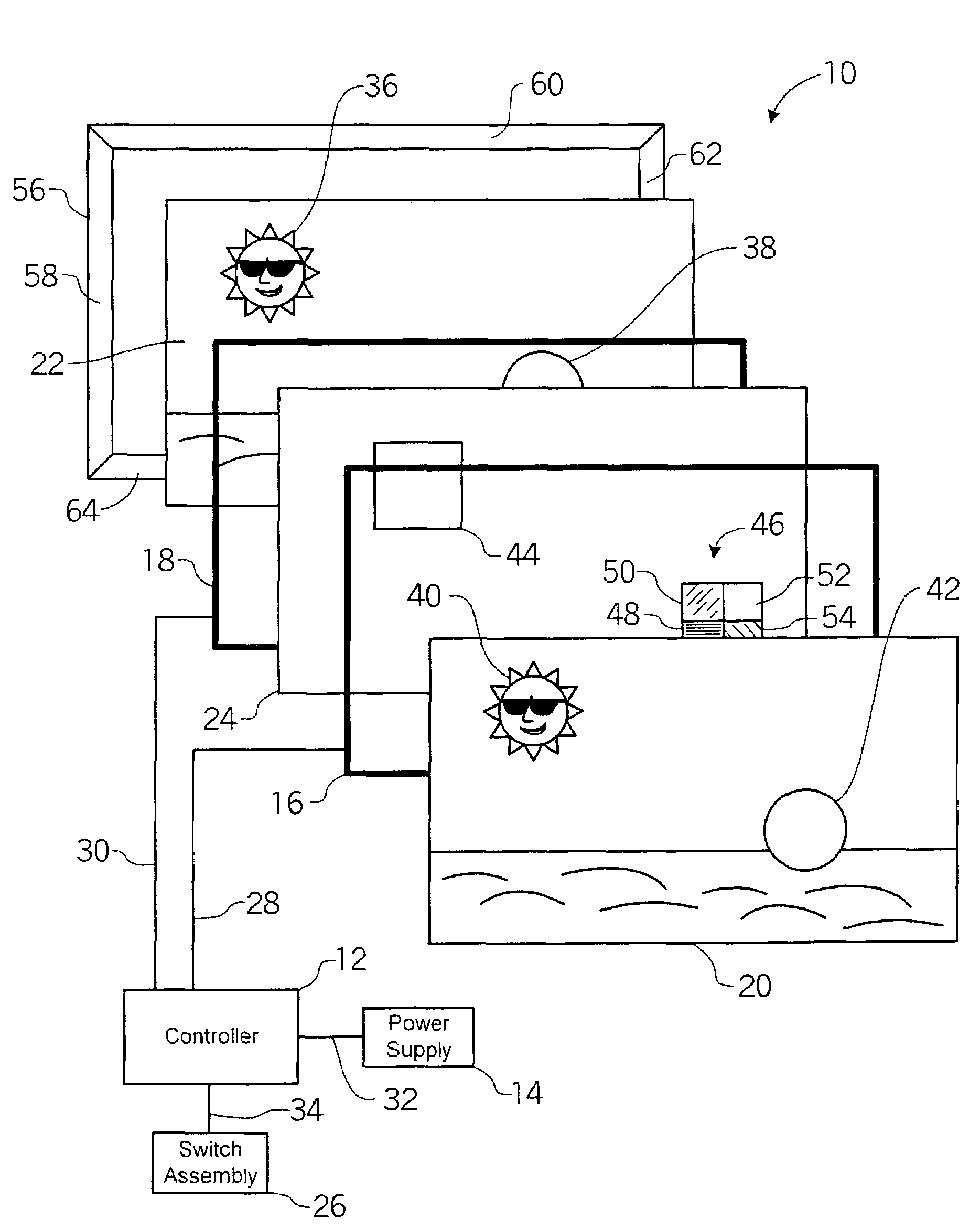
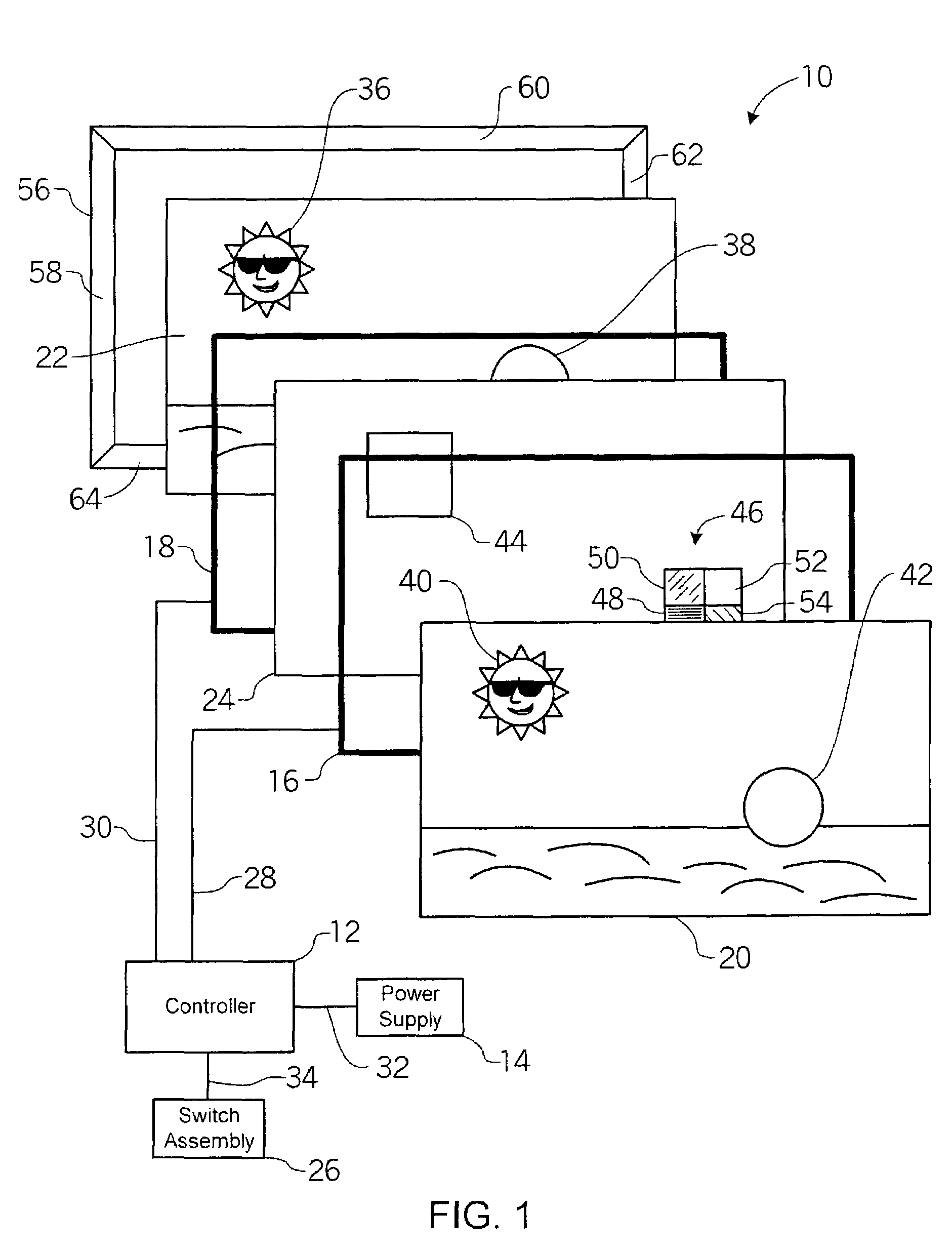
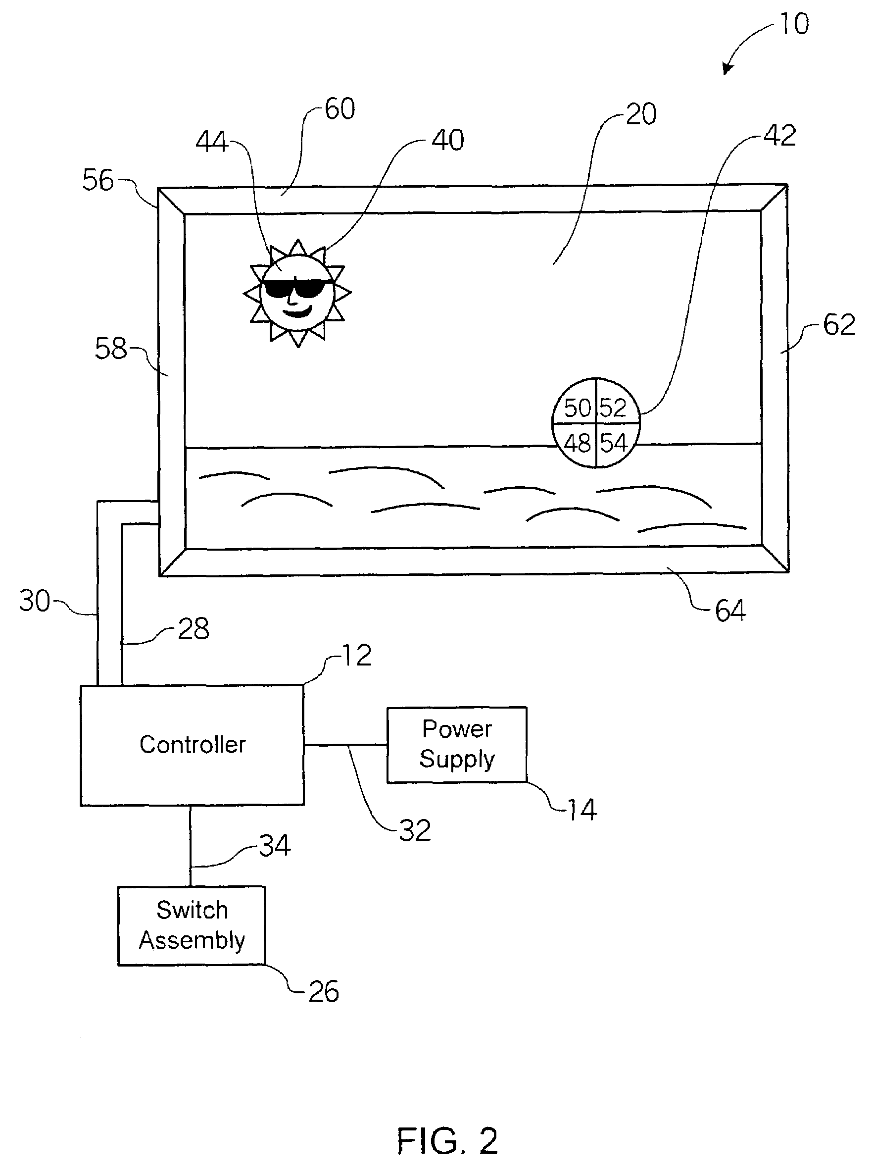
[0015]FIGS. 1 and 2 illustrate an animated sign assembly 10 in accordance with a preferred embodiment of the invention. As shown, sign assembly 10 may include a controller or control module 12, a power supply 14, a plurality, e.g., a pair, of electrically conductive, transparent or translucent sheets 16, 18, and a sheet 24 of electronic paper, which will be described more fully and completely below, and which is sandwiched between sheets 16, 18. A pair of image layers 20, 22 may be selectively printed on, disposed over, or otherwise attached to sheets 16, 18, respectively. In the preferred embodiment, a frame assembly 56 frictionally engages image layers 20, 22 and / or sheets 16, 18, thereby holding together image layers 20, 22, sheets 16, 18 and electronic paper 24. A user-operated control, e.g., a switch assembly 26, may be used to control the sign assembly 10.

[0016]In the preferred embodiment of the invention, control module or controller 12 may be a simple electrical circuit comp...


PUM


Abstract

A sign assembly 10 that implements electronic paper to display an animated image. The sign assembly includes a controller 12, a power supply 14, a pair of substantially transparent, electrically conductive sheets 16, 18, and a sheet of electronic paper 24, which is sandwiched between sheets 16, 18. Image layers 20, 22 are imprinted on the sheets 16, 18, or are alternatively held frictionally adjacent to sheets 16, 18 by a frame assembly 56. Image layers 20, 22 include substantially transparent regions 36, 38, 40 and 42 in which sheet 24 is visible. The conductive sheets 16, 18 are connected to controller 12 which provides an electronic signal which is varied over time resulting in the display of an animated or changing image which may be visible when viewed from one or both sides of the sign assembly 10.

Description

[0001]This application claims priority to and is a continuation of, U.S. patent application Ser. No. 09 / 944,860 entitled “Animated Sign Assembly” filed Aug. 31, 2001 now U.S. Pat. No. 6,588,131, and incorporates it by reference in its entirety.FIELD OF THE INVENTION[0002]This invention generally relates to an animated sign assembly and more particularly, to a sign assembly which utilizes electronic paper to provide a selectively animated image in a simple and cost-effective manner.BACKGROUND OF THE INVENTION[0003]Signs are often used to identify, promote and / or advertise goods and services. Conventional signs typically utilize one or more static or unchanging images to provide advertising or identification of a product or service.[0004]Efforts have been made to integrate electrical components into signs in order to provide animated or dynamic images and advertisements. By way of example, electrically-animated signs have been constructed using arrays of electrically-controlled lights...

Claims


Application Information

Patent Timeline
IPC IPC(8): G06F9/00G02B26/02G09F9/37G09G3/00
CPCG02B26/026G09F9/372G09G3/001
Inventor O'CONNELL, JR., CHARLES
Owner XEROX CORP
Learn More