Injection molded resin gear and injection molded resin rotating body

a technology of injection molding resin and rotating body, which is applied in the direction of dough shaping, manufacturing tools, hoisting equipment, etc., can solve the problems of deteriorating gear strength, affecting the precision of tooth profile, and affecting the strength of gear, so as to effectively inhibit the occurrence of weld lines

Active Publication Date: 2008-08-05
ENPLAS CORP
View PDF9 Cites 21 Cited by
  • Summary
  • Abstract
  • Description
  • Claims
  • Application Information

AI Technical Summary

Benefits of technology

[0013]It is therefore an object of the present invention to eliminate the aforementioned problems and to provide an injection molded resin gear or an injection molded resin rotation body capable of effectively inhibiting the occurrence of weld lines when it is formed by using one or a plurality of pin point gates.

Problems solved by technology

If the weld lines 53 are produced on the injection molded article (the injection molded resin gear 50), there are some cases where the weld lines 53 do not only have a bad influence on the precision of tooth profile, but they also have a bad influence the strength of the gear.
In particular, if the resin material to be injected is a reinforced plastic containing glass or carbon fibers, it is known that the strength of the gear is deteriorated by 40 to 60%.
However, if the ring-shaped gate 54 is used for injection molding, the amount of the resin material remaining in the ring-shaped gate 54 after injection molding is larger than that if the pin point gates 51 are used for injection molding, and the amount of wasteful resin material (resin material which is not used as a product and which is cut off from the product) is larger than that if the pin point gates 51 are used for injection molding, so that the yield of the resin material is deteriorated.
In addition, in the case of the product (the injection molded resin gear 50) formed by using injection molding the ring-shaped gate 54, after the ring-shaped gate 54 is cut off, it is require to machine and scrape the cut scar of the ring-shaped gate 54 off, so that there is a problem in that the working cost is higher than that in the case of the product (the injection molded resin gear 50) formed by injection molding using the pin point gates 51.
However, the techniques disclosed in Japanese Patent Laid-Open Nos. 2-44701 and 8-132542 can not sufficiently reduce the weld lines 53 which are shown in FIG. 18 and which are produced in the joining portions of parts of the resin material, which are injected from adjacent two of the pin point gates 51, on the web 52 for connecting a rim 55, on which teeth 55 are formed, to a shaft supporting portion 57 into which a shaft is fitted, so that it is not possible to satisfy the strength of the web 52 and the precision of tooth profile to such an extent that they are required on the market in recent years.

Method used


Image

  • Injection molded resin gear and injection molded resin rotating body
  • Injection molded resin gear and injection molded resin rotating body
  • Injection molded resin gear and injection molded resin rotating body

Examples


Embodiment Construction

[0047]Referring now to the accompanying drawings, the preferred embodiments of the present invention will be described below in detail.

[First Preferred Embodiment]

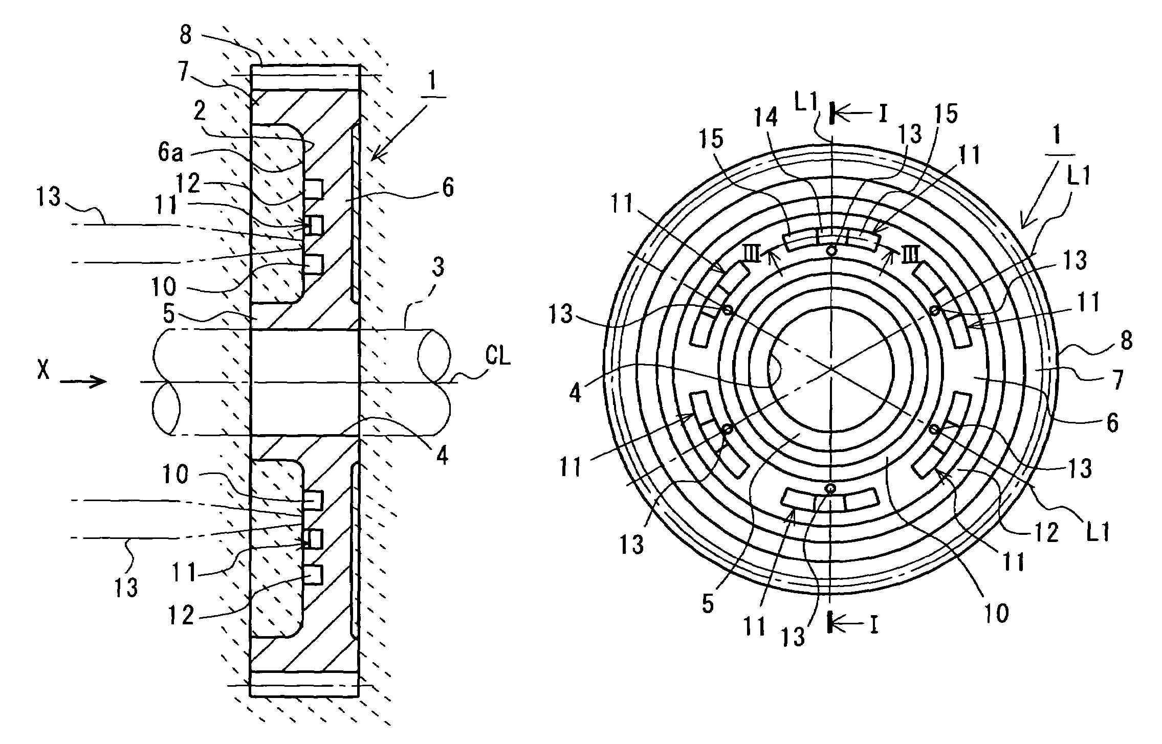
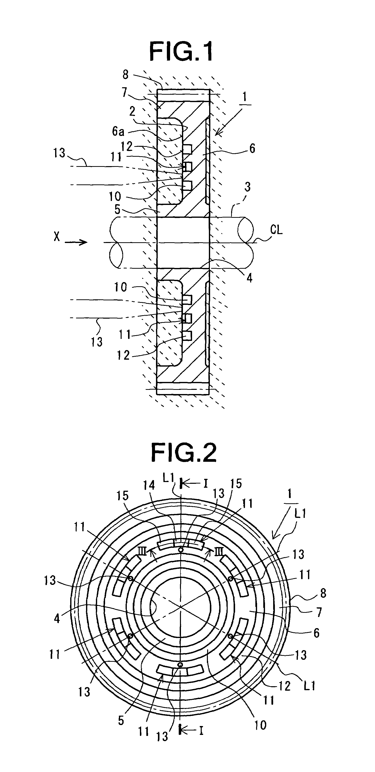
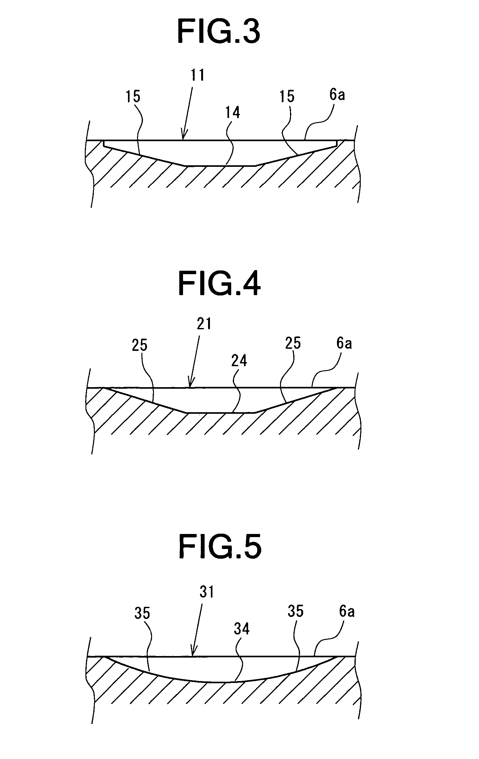
[0048]FIGS. 1 through 3 show the first preferred embodiment of an injection molded resin gear 1 according to the present invention. FIG. 1 is a longitudinal section of the injection molded resin gear 1 (a sectional view taken along line I-I of FIG. 2), and FIG. 2 is a left side view of the injection molded resin gear 1 (viewed in the direction of arrow X in FIG. 1). FIG. 3 is an enlarged sectional view of a resin flow velocity regulating groove taken along line III-III of FIG. 2. In FIG. 1, a cavity 2 for molding the injection molded resin gear 1 is schematically shown by slanting dotted lines.

[0049]The injection molded resin gear 1 shown in these figures is molded by injecting a resin material, such as polyacetal, polyamide, polyphenylene sulfide or polybutylene terephthalate, which contains reinforced fibers (glass or ca...


PUM

PropertyMeasurementUnit
velocityaaaaaaaaaa
flow velocityaaaaaaaaaa
weightaaaaaaaaaa

Abstract

An injection molded resin gear 1, which is molded by injecting a resin material from a plurality of pinpoint gates 13 into a cavity 2 of a die, includes a rim 7 having teeth 8 on its outer periphery, a shaft supporting portion 5 into which a shaft 3 is to be fitted, a web 6 extending in radial directions to connect the rim 7 to the shaft supporting portion 5, and a plurality of resin flow velocity regulating grooves 11. When the resin material injected from the pin point gates 13 flows in the cavity 2 outwardly in radial directions, the uniformity of the flow velocity of the resin material passing over portions of the cavity 2 corresponding to the resin flow velocity regulating grooves 11 is improved, and the uniformity of the flow velocity of the resin material passing over a portion of the cavity 2 corresponding to an outside circumferential groove 12 is more sufficiently improved, so that the uniformity of the flow velocity of the resin material in a portion of the cavity 2 corresponding to the web 6 is improved before the resin material reaches a portion of the cavity 2 corresponding to the rim 7.

Description

BACKGROUND OF THE INVENTION[0001]1. Field of the Invention[0002]The present invention generally relates to an injection molded resin gear and an injection molded resin rotating body. More specifically, the invention relates to an injection molded resin gear for use in power transmission devices for various automotive parts, industrial equipments and precision instruments, and an injection molded resin rotating body, such as an injection molded resin gear, sprocket, pulley or roller.[0003]2. Description of the Prior Art[0004]In recent years, automotive parts operating by driving force from a driving source, such as a motor, has many resin gears, which are formed by injection molding, in order to reduce the weight and operation noises thereof.[0005]FIG. 17 is a longitudinal section of such an injection molded resin gear 50, and FIG. 18 is a left side view of the injection molded resin gear 50 of FIG. 17, which is viewed from the left side of FIG. 17. The injection molded resin gear 50...

Claims


Application Information

Patent Timeline
Patent Type & Authority Patents(United States)
IPC IPC(8): F16H55/17B29C45/00B29C45/37B29D15/00B29L15/00F16H55/06
CPCB29C45/0025B29C45/0046B29D15/00F16H55/06Y10S74/10F16H2055/065Y10T74/19851B29L2015/003
Inventor MIYASAKA, SHOJI
Owner ENPLAS CORP
Why Eureka
Try Eureka