Piezoelectric substrate for a saw device

a saw and substrate technology, applied in the field of surface acoustic wave (saw) devices, can solve the problems of litany of manufacturing problems, achieve the effects of reducing bending and warping, reducing expansion and contraction of piezoelectric substrates, and high young 's modulus

Active Publication Date: 2008-08-05
QORVO US INC
View PDF6 Cites 23 Cited by
  • Summary
  • Abstract
  • Description
  • Claims
  • Application Information

AI Technical Summary

Benefits of technology

[0007]The present invention provides a composite structure having a supporting substrate between a piezoelectric substrate and a compensation layer. The materials used to form the piezoelectric substrate and the compensation layer in isolation have higher thermal coefficients of expansion (TCE) relative to the TCE of the materials forming the supporting substrate. Once the piezoelectric structure is created, the piezoelectric substrate and the compensation layer tend to expand and contract in a similar manner as temperature changes. As such, the expansion and contraction forces applied to the supporting substrate by the piezoelectric substrate due to temperature changes are substantially countered by opposing forces applied by the compensation layer. Since the expansion or contraction forces on opposing faces of the supporting substrate, applied to the supporting substrate by the piezoelectric substrate and the compensation layer are similar, and thus counter one another, the composite structure resists bending or warping as temperature changes. Reducing bending and warping reduces expansion and contraction of the piezoelectric substrate, and thus the effective TCE of the piezoelectric substrate. Preferably, the supporting substrate has a relatively high Young's Modulus to provide sufficient rigidity to withstand the forces applied by the piezoelectric substrate and the compensation layer, and thus further reduces expansion and contraction of the piezoelectric substrate.
[0008]Since providing the compensation layer on the opposite side of the supporting substrate reduces the effective TCE of the piezoelectric substrate, the amount of expansion and contraction along the surface of the piezoelectric substrate as temperature changes is reduced. Therefore, the change in spacing, or pitch, between the interdigitated fingers of the IDTs and the reflectors as temperature changes is reduced. Reducing the change in spacing between the interdigitated fingers reduces the effective thermal coefficient of frequency (TCF) of the piezoelectric substrate to improve overall frequency response of the IDTs and the reflectors, and thus the SAW device, as temperature changes. At the same time, the amount of stress in the region of ultrasonic propagation on the surface of the piezoelectric substrate is increased leading to a stronger change in elastic properties, and thus, leading to favorable changes in ultrasonic velocity. Applying larger stress to the piezoelectric substrate leads to improvement of the TCV to further improve the overall frequency response of the IDTs and the reflectors, and thus the SAW device, as temperature changes.

Problems solved by technology

Bent and warped substrates lead to a litany of manufacturing issues during photolithography, dicing, mounting, packaging, and integration of the SAW devices 10 with other semiconductor components.

Method used


Image

  • Piezoelectric substrate for a saw device
  • Piezoelectric substrate for a saw device
  • Piezoelectric substrate for a saw device

Examples


Embodiment Construction

[0017]The embodiments set forth below represent the necessary information to enable those skilled in the art to practice the invention and illustrate the best mode of practicing the invention. Upon reading the following description in light of the accompanying drawing figures, those skilled in the art will understand the concepts of the invention and will recognize applications of these concepts not particularly addressed herein. It should be understood that these concepts and applications fall within the scope of the disclosure and the accompanying claims.

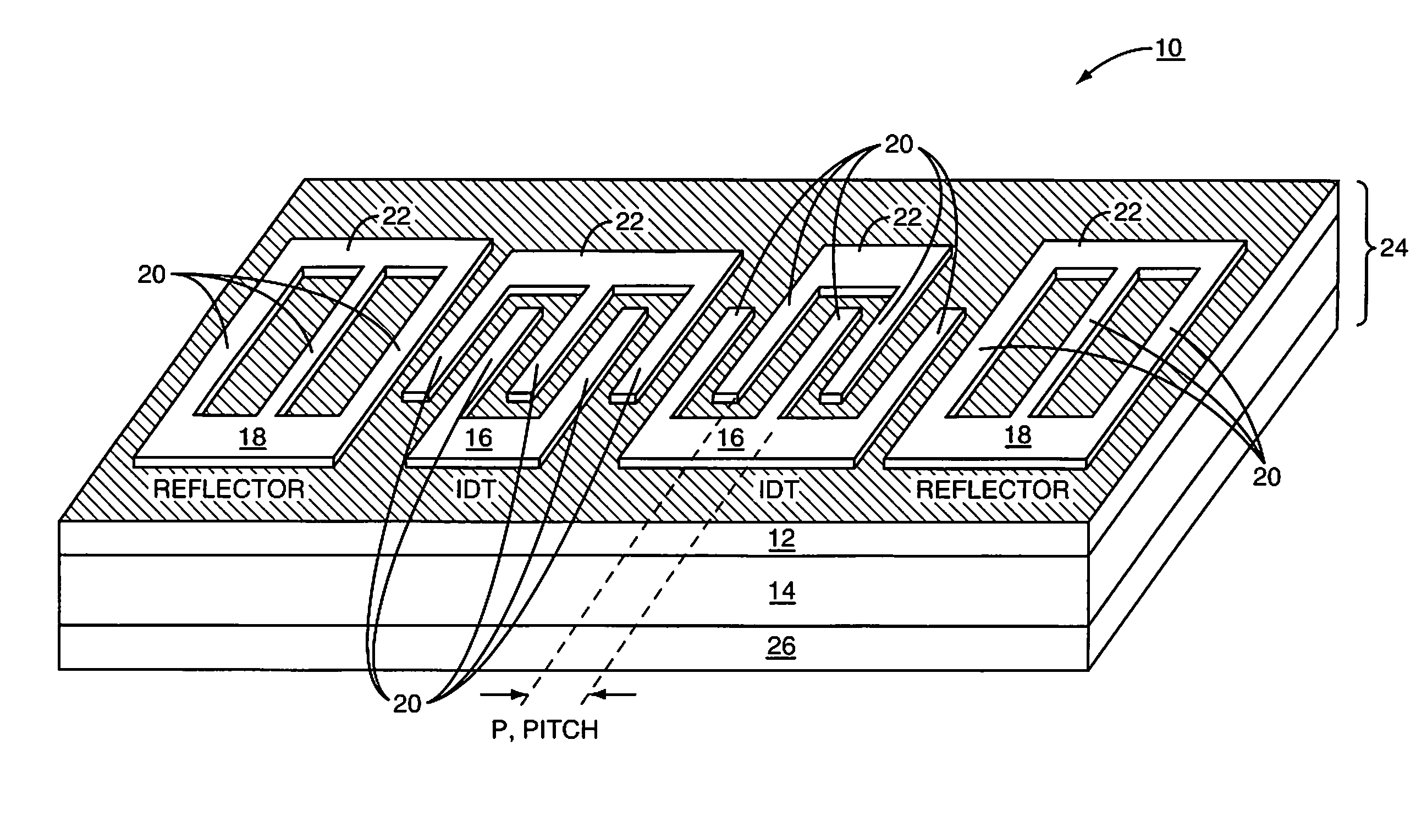
[0018]With reference to FIG. 3, a SAW device 10 is illustrated according to one embodiment of the present invention. The SAW device 10 will generally include a piezoelectric substrate 12, which has a surface on which various types of SAW elements, such as IDTs and reflectors, may be formed. The piezoelectric substrate 12 resides on a supporting substrate 14. As illustrated in this example, a dual-mode SAW (DMS) device is provided,...


PUM

PropertyMeasurementUnit
Young's Modulusaaaaaaaaaa
thicknessaaaaaaaaaa

Abstract

The present invention provides a composite structure having a supporting substrate between a piezoelectric substrate and a compensation layer. The materials used to form the piezoelectric substrate and the compensation layer in isolation, have higher thermal coefficients of expansion (TCE) relative to the TCE of the materials forming the supporting substrate. Once the composite structure is created, the piezoelectric substrate and compensation layer tend to expand and contract in a similar manner as temperature changes. The expansion and contraction forces applied to the supporting substrate by the piezoelectric substrate due to temperature changes are substantially countered by similar opposing forces applied by the compensation layer, resulting in the opposing forces substantially counteracting one another. Due to the counteraction, the composite structure resists bending or warping, reducing expansion and contraction and increasing stress of the piezoelectric substrate, and thus reducing the effective TCE and TCF of the piezoelectric substrate.

Description

FIELD OF THE INVENTION[0001]The present invention relates to a Surface Acoustic Wave (SAW) device, and more particularly to a SAW device formed on an improved piezoelectric substrate.BACKGROUND OF THE INVENTION[0002]Surface acoustic wave (SAW) devices use one or more interdigitated transducers (IDTs), and perhaps reflectors, provided on a piezoelectric substrate to convert acoustic waves to electrical signals and vice versa. SAW devices are often used in filtering applications for high-frequency signals. Of particular benefit is the ability to create low loss high order bandpass and notch filters without employing complex electrical filter circuits, which may require numerous active and passive components. A common location for a filtering application is in the transceiver circuitry of wireless communication devices.[0003]With reference to FIG. 1, a typical SAW device 10 on a temperature compensated bonded substrate is illustrated. The SAW device 10 will generally only include a pie...

Claims


Application Information

Patent Timeline
Patent Type & Authority Patents(United States)
IPC IPC(8): H01L41/08
CPCH03H9/02574H03H9/02614Y10T29/42Y10T29/49155
Inventor BHATTACHARJEE, KUSHALZHGOON, SERGEI
Owner QORVO US INC
Why Eureka
Try Eureka