
Voltage up-conversion circuit using low voltage transistors

a voltage up conversion and transistor technology, applied in logic circuit coupling/interface arrangement, instruments, apparatus without intermediate ac conversion, etc., can solve the problems of increasing system integration complexity and system cost, increasing manufacturing cost, and increasing fabrication process complexity of transistors, and achieve low cost

Active Publication Date: 2008-08-05
SKYWORKS SOLUTIONS INC
View PDF2 Cites 124 Cited by
  • Summary
  • Abstract
  • Description
  • Claims
  • Application Information

AI Technical Summary

Benefits of technology

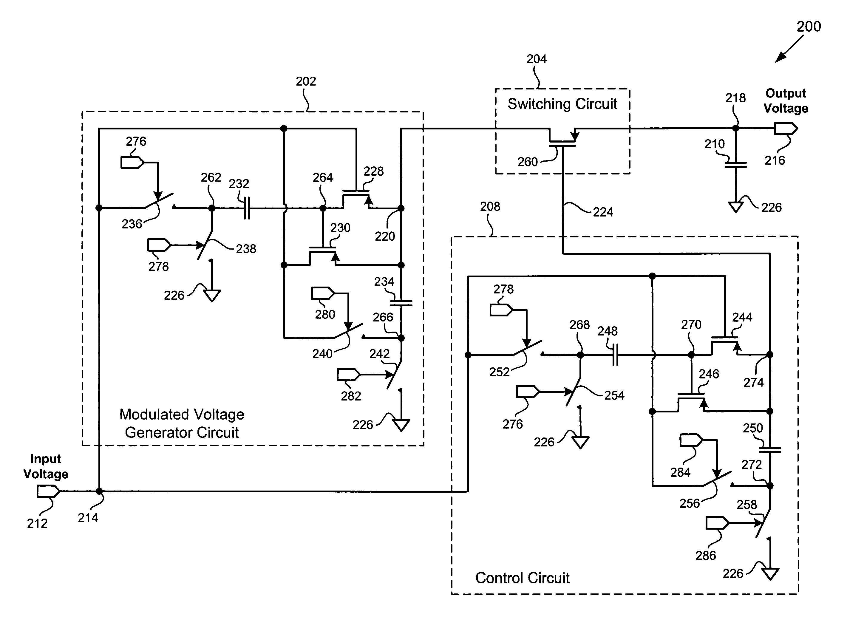
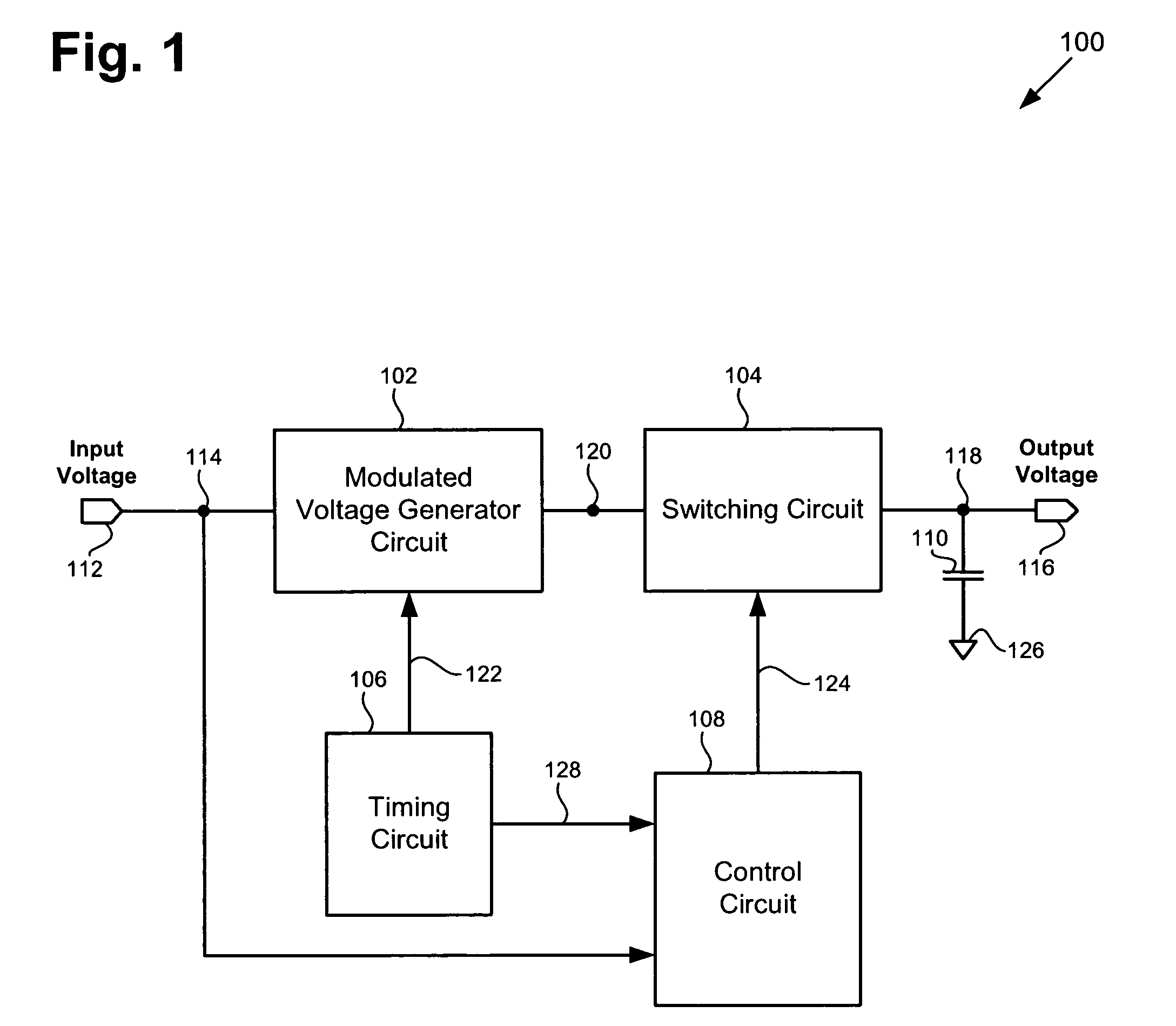
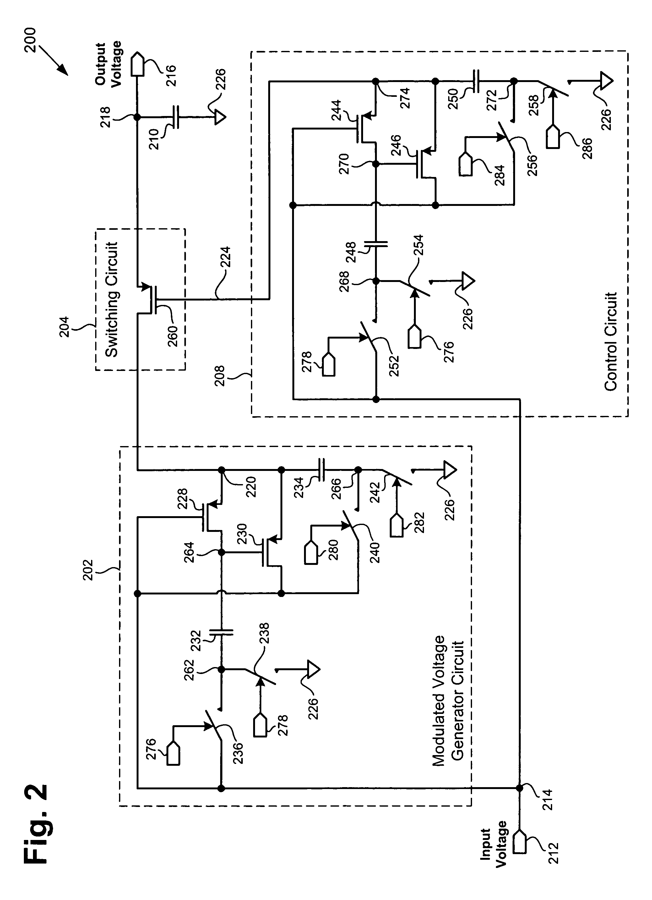
The present invention is about a circuit that converts low voltage to high voltage for use in portable electronic devices. The circuit uses low cost components and is efficient in converting voltage. It includes a modulated voltage generator circuit with a transistor and a switching circuit to connect or disconnect the modulated voltage to a load capacitor. The circuit also has a control circuit to generate a control voltage to control the switching circuit. The timing circuit causes the modulated voltage to be generated and the control circuit to connect or disconnect the modulated voltage to the load capacitor only when it is at a high level. The technical effect of this invention is to provide a low cost and efficient voltage up-conversion circuit for use in portable electronic devices.

Problems solved by technology

However, both of these approaches typically require high voltage transistors, such as 5 volt transistors, to handle high output voltage.
Although 5 volt transistors can be added for a voltage up-conversion circuit in the fabrication process, adding 5 volt transistors increases fabrication process complexity, which increases manufacturing cost.
However, this approach undesirably increases system integration complexity and system cost.

Method used


Image

  • Voltage up-conversion circuit using low voltage transistors
  • Voltage up-conversion circuit using low voltage transistors
  • Voltage up-conversion circuit using low voltage transistors

Examples


Embodiment Construction

[0015]The present invention is directed to a voltage up-conversion circuit using low voltage transistors. The following description contains specific information pertaining to the implementation of the present invention. One skilled in the art will recognize that the present invention may be implemented in a manner different from that specifically discussed in the present application. Moreover, some of the specific details of the invention are not discussed in order not to obscure the invention. The specific details not described in the present application are within the knowledge of a person of ordinary skill in the art.

[0016]The drawings in the present application and their accompanying detailed description are directed to merely exemplary embodiments of the invention. To maintain brevity, other embodiments of the invention which use the principles of the present invention are not specifically described in the present application and are not specifically illustrated by the present...


PUM


Abstract

According to one exemplary embodiment, a voltage up-conversion circuit includes a modulated voltage generator circuit, where the modulated voltage generator circuit is configured to receive an input voltage and generate a modulated voltage, and where the modulated voltage generator circuit includes at least one transistor. The voltage up-conversion circuit further includes a switching circuit coupled to the modulated voltage generator circuit, where the switching circuit is configured to couple the modulated voltage to a load capacitor when the modulated voltage is at a high level and decouple the modulated voltage to the load capacitor when the modulated voltage is at a low level. In the voltage up-conversion circuit, the load capacitor reaches a voltage greater a breakdown voltage of the at least one transistor in the modulated voltage generator circuit. The breakdown voltage can be a reliability breakdown voltage.

Description

BACKGROUND OF THE INVENTION[0001]1. Field of the Invention[0002]The present invention is generally in the field of electrical circuits. More particularly, the invention is in the field of voltage up-conversion circuits.[0003]2. Related Art[0004]Portable and mobile electronic devices, such as wireless communication devices, typically include analog and digital systems that require multiple operating voltages. The multiple operating voltages required by analog and digital systems are typically provided by on-chip DC-DC voltage converters, which can utilize a single external voltage source, such as a battery. However, battery voltage can drop significantly below 5 volts, which is a required operating voltage for some system interface circuits. As a result, analog and digital systems in portable and mobile electronic devices typically require on-chip voltage up-conversion.[0005]Voltage up-conversion is typically provided by using switching regulators, such as a Cuk converters, or switch...

Claims


Application Information

Patent Timeline
Patent Type & Authority Patents(United States)
IPC IPC(8): G05F1/00
CPCH02M3/07G05F1/00H03K19/0175
Inventor ZHAO, BIN
Owner SKYWORKS SOLUTIONS INC
Learn More