Apparatus and method for reducing anhydrous ammonia application by optimizing distribution

an ammonia application and distribution method technology, applied in lighting and heating apparatus, combustion types, dental surgery, etc., can solve the problems of reduced yield variability, less nitrate leaching, and low ammonia application rates, so as to improve the accuracy of distribution manifolds, less nitrate leaching, and the effect of reducing the application ra

Inactive Publication Date: 2008-08-12
IOWA STATE UNIV RES FOUND
View PDF10 Cites 3 Cited by
  • Summary
  • Abstract
  • Description
  • Claims
  • Application Information

AI Technical Summary

Benefits of technology

[0017]The present invention relates to a distribution manifold for distributing a gas and liquid phase substance from a single inlet to multiple outlets with reduced distribution variation. In one aspect of the invention, an apparatus comprises a body, an inlet, a plurality of outlets, a fluid pathway between inlet and outlets, and mechanism to move the exit of the pathway in a controlled manner past the outlets. In one aspect, the mechanism is an impeller, being rotatable and having a surface at an angle to flow of the substance (e.g. external flighting or a spiral groove), allows the substance to pass from the inlet and at the surface as the impeller rotates, to then distribute the substance to the outlets. Impeller rotation can be induced by pressure of the incoming substance against the impeller surface(s). The fluid pathway can be multiple pathways. Optionally, rotation can be powered by a motor or other actuator.
[0019]Improved accuracy in distribution manifolds can result in lower ammonia application rates resulting in less nitrate leaching and reduced yield variability. Recommendations can also be made to achieve the most even fertilizer distribution at different application rates.

Problems solved by technology

Improved accuracy in distribution manifolds can result in lower ammonia application rates resulting in less nitrate leaching and reduced yield variability.

Method used


Image

  • Apparatus and method for reducing anhydrous ammonia application by optimizing distribution
  • Apparatus and method for reducing anhydrous ammonia application by optimizing distribution
  • Apparatus and method for reducing anhydrous ammonia application by optimizing distribution

Examples


Embodiment Construction

[0028]For a better understanding of the invention, one exemplary embodiment will now be described in detail. It is to be understood that this is but one form the invention can take and does not limit the scope of the invention. Variations obvious to those skilled in the art will be included within the invention.

A. General Environment of Use of the Invention

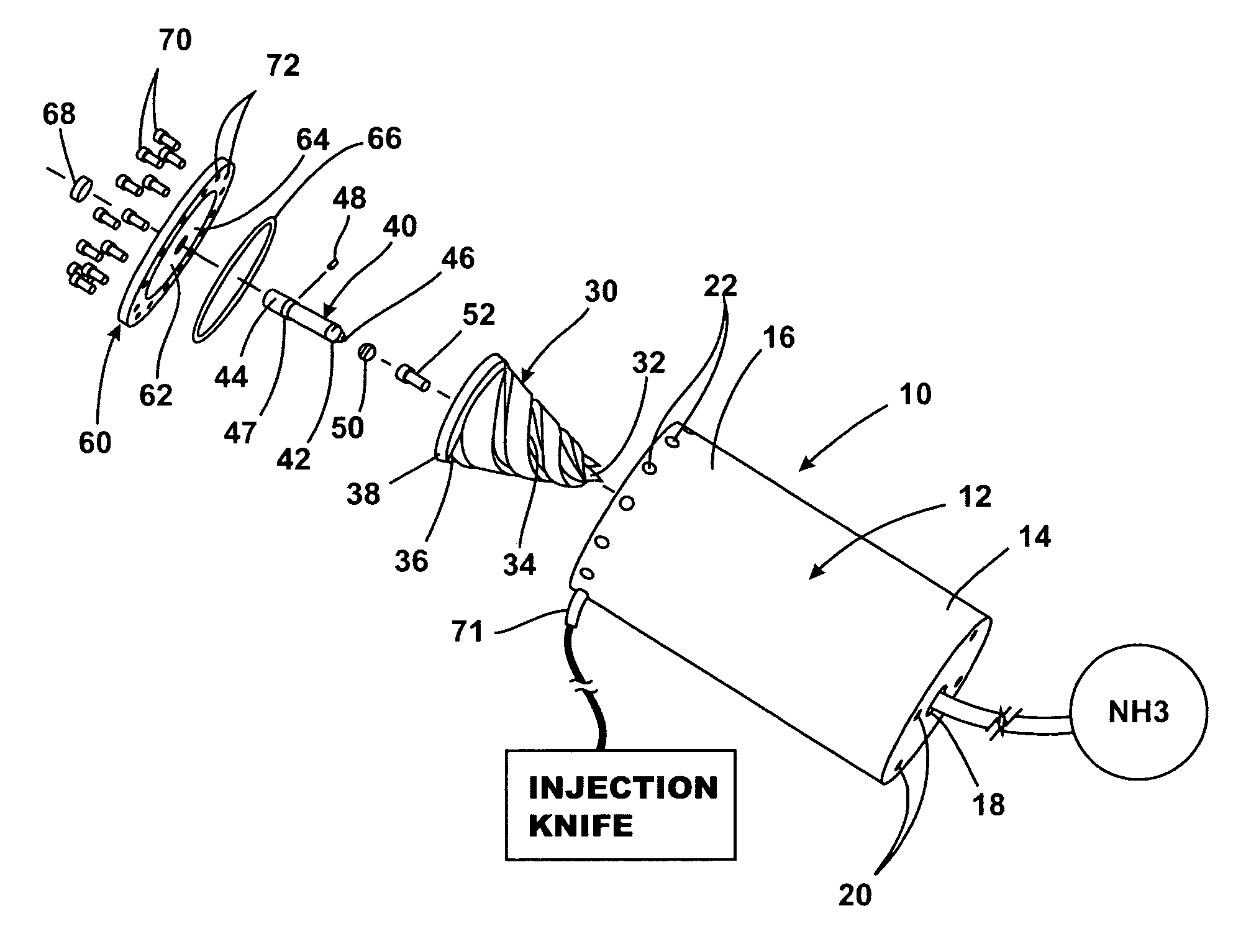
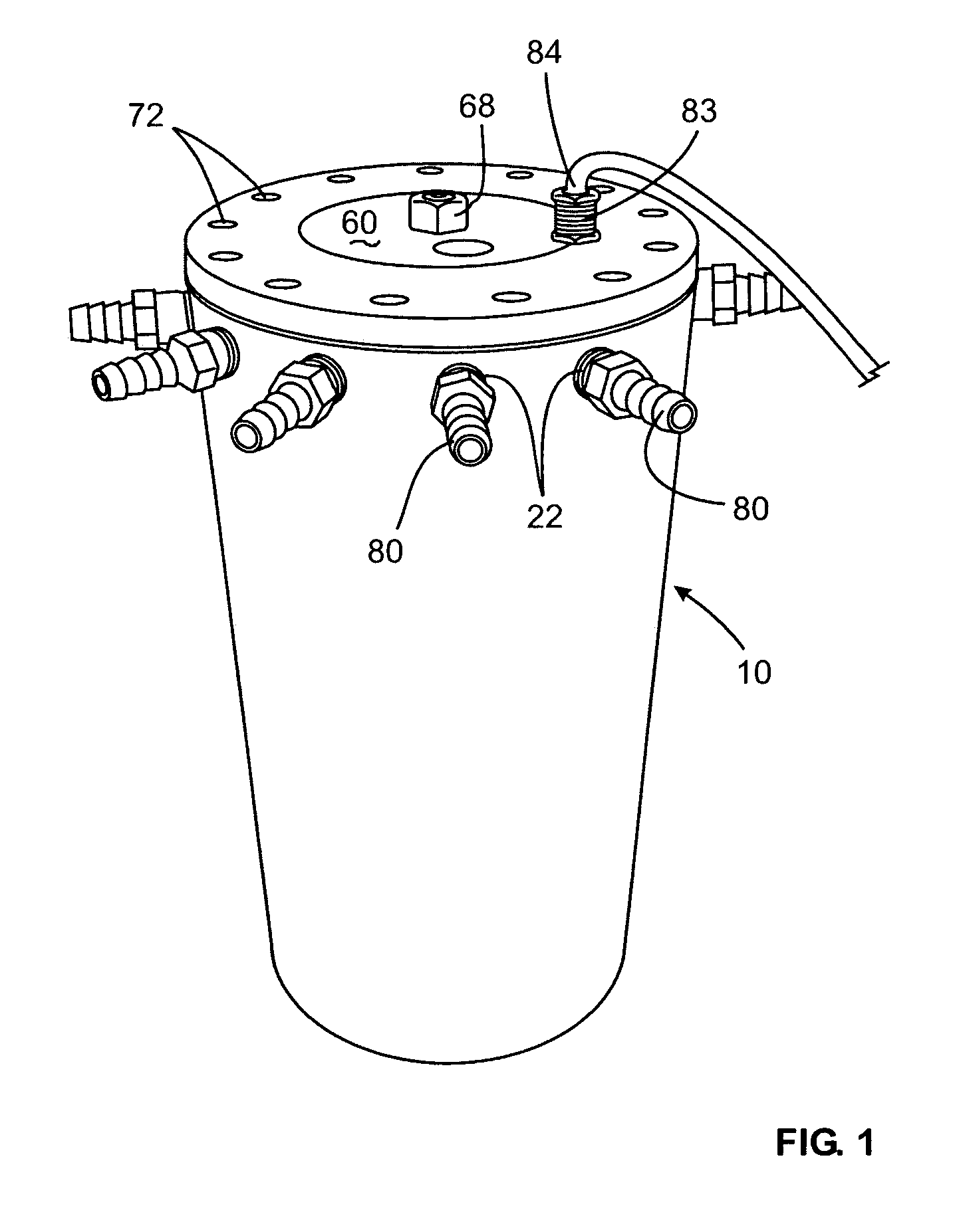
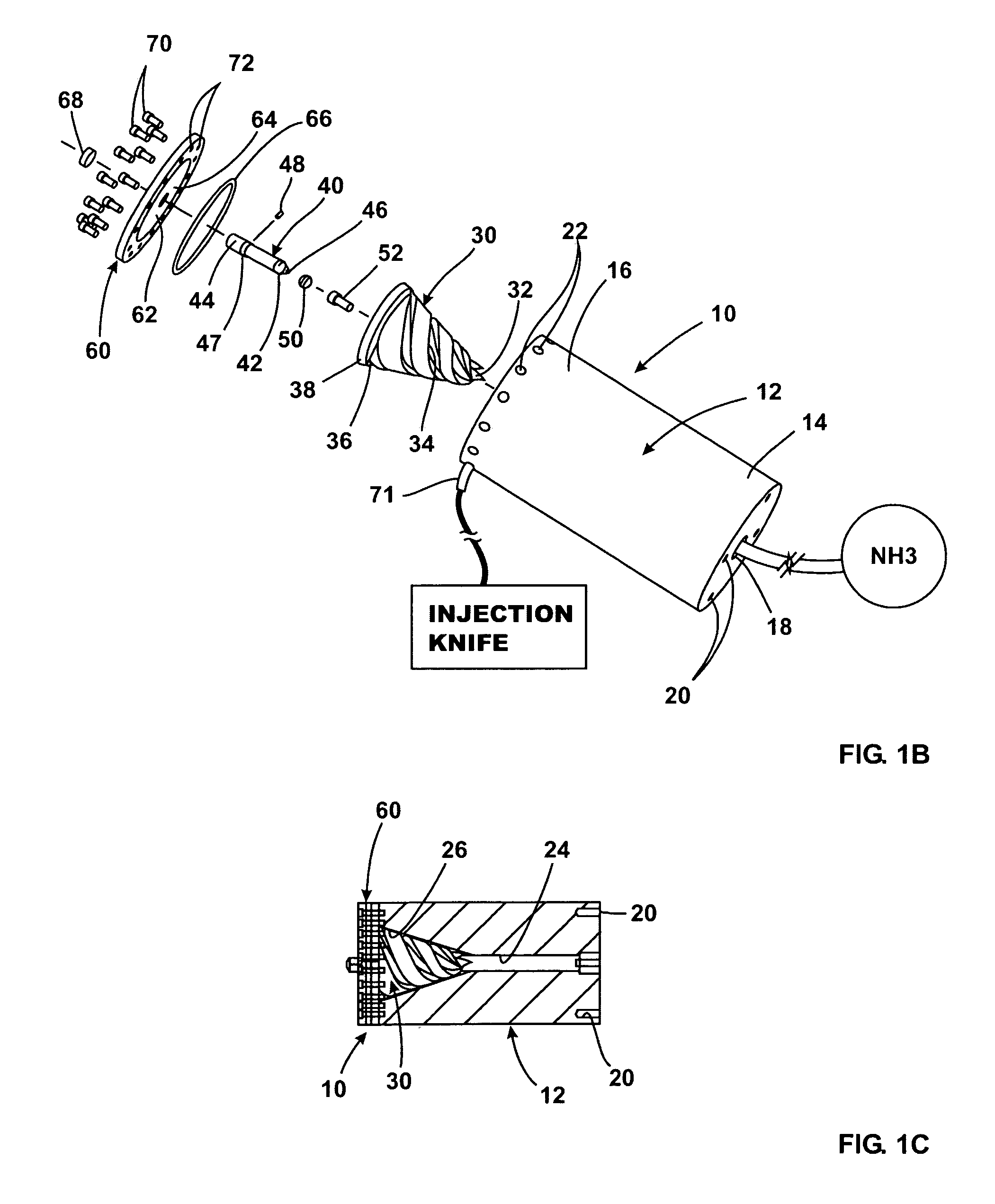
[0029]An embodiment of the invention is here referred to as distribution manifold 10. Manifold 10 includes an input adapted to be connected to a pressurized source of anhydrous ammonia (see FIG. 1B), and has a plurality of fittings 80 radially distributed around the manifold body 12 (see FIG. 1A) that can be operatively connected to hoses 71 which, in turn, are connected at distal ends to individual injection knives for an anhydrous ammonia injection system (see FIG. 1B where, for simplicity, just one fitting 80 from an outlet 22 is diagrammatically illustrated connected by a hose 71 to an injection knife).

[0030]Distribution manif...


PUM


Abstract

An apparatus, method, and system for distributing gas and / or liquid phase substance from an inlet to multiple outlets with reduced variations and distribution. The apparatus includes a body having an inlet and a plurality of outlets. In one aspect, a rotatable impeller is positioned between inlet and plurality of outlets. The impeller includes a spiral fluid pathway relative to direction of substance through the inlet so that the substance passes through the impeller and is distributed to the outlets through a spinning impeller.

Description

I. CROSS-REFERENCE TO RELATED APPLICATIONS[0001]This application is a Continuation of U.S. Ser. No. 10 / 620,925 filed Jul. 16, 2003 which is a non provisional of application U.S. Ser. No. 60 / 396,763 filed Jul. 17, 2002, both of which are hereby incorporated by reference in their entirety.II. BACKGROUND OF THE INVENTION[0002]Application or injection of chemicals, such as fertilizers, on or into the soil, is commonly used to enhance growth and yield for agricultural plants. In come cases, such substances are in fluid-form (liquid or gaseous phase, as opposed to solid phase). Apparatus is required to convey the substance from a bulk storage container to the ground.[0003]One example is the injection of anhydrous ammonia (NH3) (a gas at ambient temperatures and pressures) into the ground. Normally, the substance is kept under pressure in liquid phase in a large bulk holding container or tank. What are called knives have discharge ends that are dragged through the ground. A valving and dis...

Claims


Application Information

Patent Timeline
Patent Type & Authority Patents(United States)
IPC IPC(8): A01C23/00B05B1/14B05B1/34B05B3/04
CPCA01C23/007A01C23/024B05B3/04B05B3/02B05B1/14
Inventor HANNA, H. MARKBOYD, PAUL M.
Owner IOWA STATE UNIV RES FOUND
Why Eureka
Try Eureka