
Transmission containing helical gearing and bearing arrangement therefor

a technology of helical gears and transmissions, applied in the direction of toothed gearings, rigid support of bearing units, wind energy generation, etc., can solve the problems of affecting the performance of transmissions, and requiring considerable length and surface area of transmissions,

Active Publication Date: 2008-08-12
THE TIMKEN CO
View PDF16 Cites 23 Cited by
  • Summary
  • Abstract
  • Description
  • Claims
  • Application Information

AI Technical Summary

Benefits of technology

The patent text describes a wind turbine transmission system that uses helical gears to step-up the speed of rotation between the rotor and generator. The transmission system includes a housing, a planetary set, an intermediate shaft, and an output shaft. Bearings at both positions support the shafts and accommodate thrust loads in both directions. The technical effect of the patent is to provide a wind turbine transmission system that can efficiently transmit power from the rotor to the generator while minimizing noise and vibration.

Problems solved by technology

But the vanes need considerable length and surface area to capture the wind, and as a consequence they rotate at a relatively low angular velocity.
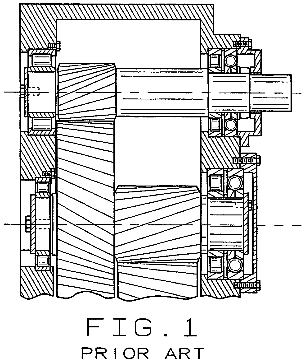
Deep groove ball bearings can experience unusual wear patterns and can fail prematurely along their raceways.
Two-row bearings, moreover, consume considerable axial space where space is at a premium.
Although adjustment of these clearances is a common and well-acknowledged practice in the transmission industry, the concern always remains in this industry over manufacturing errors or operator error during adjustment, altering the expected settings and subsequently affecting the performance of the transmission (high temperatures, poor gear contact, noise vibration, etc).

Method used


Image

  • Transmission containing helical gearing and bearing arrangement therefor
  • Transmission containing helical gearing and bearing arrangement therefor
  • Transmission containing helical gearing and bearing arrangement therefor

Examples


Embodiment Construction

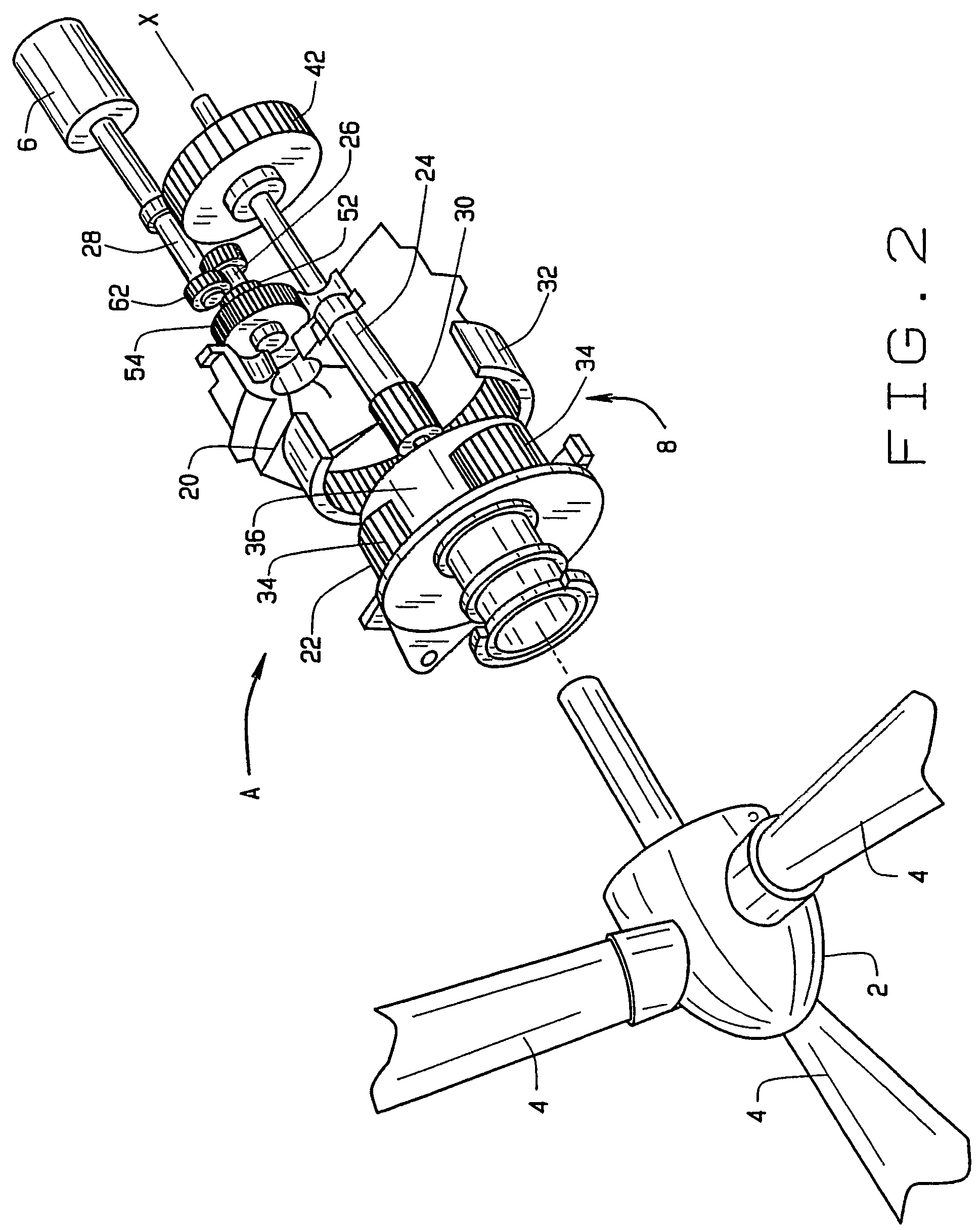
[0012]Referring now to the drawings, a wind turbine A (FIG. 2) for generating electrical energy includes a rotor 2 provided with vanes 4 against which the wind impinges to cause the rotor 2 to revolve about an axis X. The rotor 2 drives a generator 6 which produces electrical energy. But the rotor 2 is not coupled directly to the generator 4. Instead, the two are connected through a transmission 8 which effects a step-up in speed, so that the generator 4 rotates at an angular velocity considerably greater than the rotor 2.

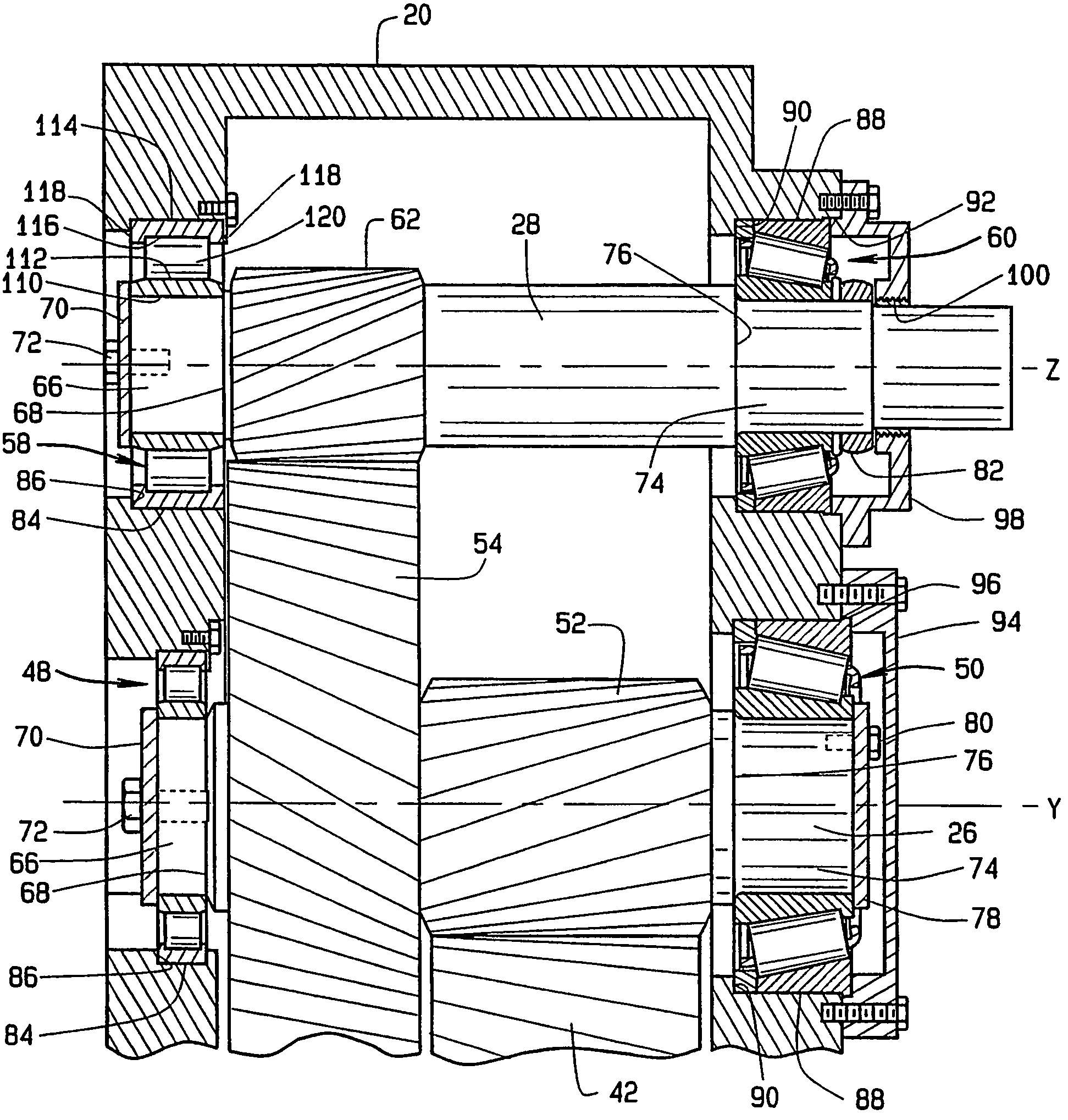
[0013]The transmission 8 includes housing 20 and within the housing 20 a planetary set 22, a drive or sun shaft 24, an intermediate shaft 26, and an output shaft 28. The rotor 2 is coupled to the planetary set 22, whereas the generator 4 is coupled to the output shaft 28.

[0014]The planetary gear set has a sun gear 30, a ring gear 32, and planet gears 34 located between and engaged with the sun and ring gears 30 and 32. It also has a carrier 36 on which the planet g...


PUM


Abstract

A transmission for a wind turbine includes a housing (20) in which two shafts (26, 28) rotate, each being supported on a locating bearing (50, 60) which transmits thrust loads to the housing as well as radial loads and on a nonlocating bearing (48, 58) which transmits only radial loads to the housing. The shafts carry helical gears (52, 52, 62) which induce thrust loads in the shafts when the shafts transmit torque. The locating bearings are unitized single row tapered roller bearings which are oriented to transmit thrust loads in the primary direction through their raceways (132, 138) and in the secondary direction through ribs (134, 144) at the ends of their rollers (146). The nonlocating bearings take the form of a single row cylindrical roller bearings which accommodate differential thermal expansion and contraction between the shafts and housing.

Description

RELATED APPLICATION[0001]This application derives and claims priority from International Application PCT / US2004 / 021265, filed Jun. 30, 2004, and published under International Publication Number WO 2005 / 005866 A1, and from U.S. provisional application 60 / 484,578, filed Jul. 2, 2003.TECHNICAL FIELD[0002]This invention relates in general to transmissions and more particularly to transmissions containing helical gears.BACKGROUND ART[0003]Wind turbines, which harness the wind to produce power, represent an ever-increasing source of electrical energy. Basically, the wind impinges against vanes on a rotor, causing the rotor to revolve, and the rotor powers an electrical generator. But the vanes need considerable length and surface area to capture the wind, and as a consequence they rotate at a relatively low angular velocity. The generator must operate at a high angular velocity if it is to remain relatively compact.[0004]To satisfy these ends, the typical wind turbine includes a transmiss...

Claims


Application Information

Patent Timeline
Patent Type & Authority Patents(United States)
IPC IPC(8): F16H57/08A47C7/74F16H37/06F03D11/00F03D11/02F16C19/36F16C19/54F16C33/60F16C35/067F16H1/08F16H57/021
CPCF03D11/0008F03D11/02F16C19/364F16C19/54F16C33/605F16H57/021F16C35/067F05B2260/4031Y10T74/19098F16H1/08Y02E10/722F16C2360/31F16C2361/61F03D80/70F03D15/00F03D15/10Y02E10/72
Inventor FOX, GERALD P.
Owner THE TIMKEN CO
Learn More