Alternating current multi-phase plasma gas generator with annular electrodes

a plasma gas generator and annular electrode technology, applied in the field of plasma gas generators, can solve the problems of uneven electrode wear, excessive path erosion along the electrode, and more than a ratio of 3:1 between end to end plasma arc length, so as to prevent spot wear

Inactive Publication Date: 2008-08-12
OAKS PLASMA +1
View PDF9 Cites 49 Cited by
  • Summary
  • Abstract
  • Description
  • Claims
  • Application Information

AI Technical Summary

Benefits of technology

[0011]A plasma generator has three elongate plasma sources connected together by a nozzle. Each elongate plasma source has an initiator end for generating an initial plasma, an annular electrode having an inner surface into which the initial plasma may form, both of which are positioned about a plasma source axis, the electrode having and a plurality of tangential gas introduction apertures for causing a formed plasma to rotate circumferentially and axially after formation. The annular electrode is followed by a plasma channel coupled to the nozzle, such that when the initiators of each plasma source is ionizing the gas, each of the three annular electrodes are excited by an electrical voltage that is substantially 120 degrees out of phase with any other electrode, thereby resulting in the formation of a plasma from one annular electrode, through the plasma channel to the nozzle, thereafter through a different plasma channel and to the related annular electrode. Through the introduction of the gas using circumferential apertures, the plasma arc attachment to the annular electrode rotates from the applied force of the introduced gas, thereby preventing spot wear on the annular electrode.

Problems solved by technology

While this results in a uniform electrode wear on the working area of the electrode, one disadvantage is that the end to end plasma arc length varies by more than a ratio of 3:1 from initiation to termination.
Another problem of this system is that as the plasma arc travels down the extent tubular electrode, radial variations in the arc spot may be minimal, leading to path erosion along the electrode which may be worn excessively in a single path compared to other regions.
The generator has no provision for uniform electrode wear.

Method used


Image

  • Alternating current multi-phase plasma gas generator with annular electrodes
  • Alternating current multi-phase plasma gas generator with annular electrodes
  • Alternating current multi-phase plasma gas generator with annular electrodes

Examples


Embodiment Construction

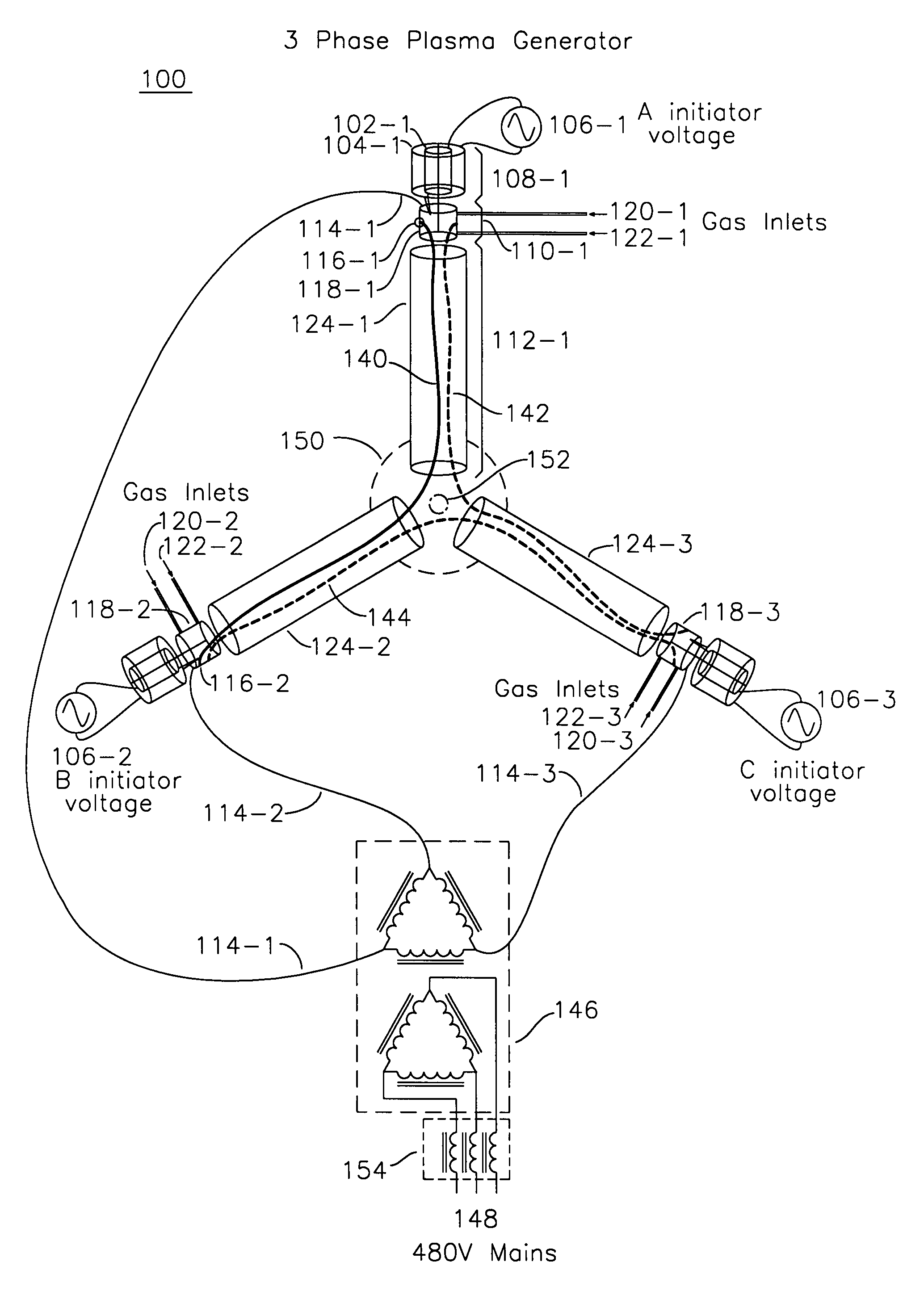
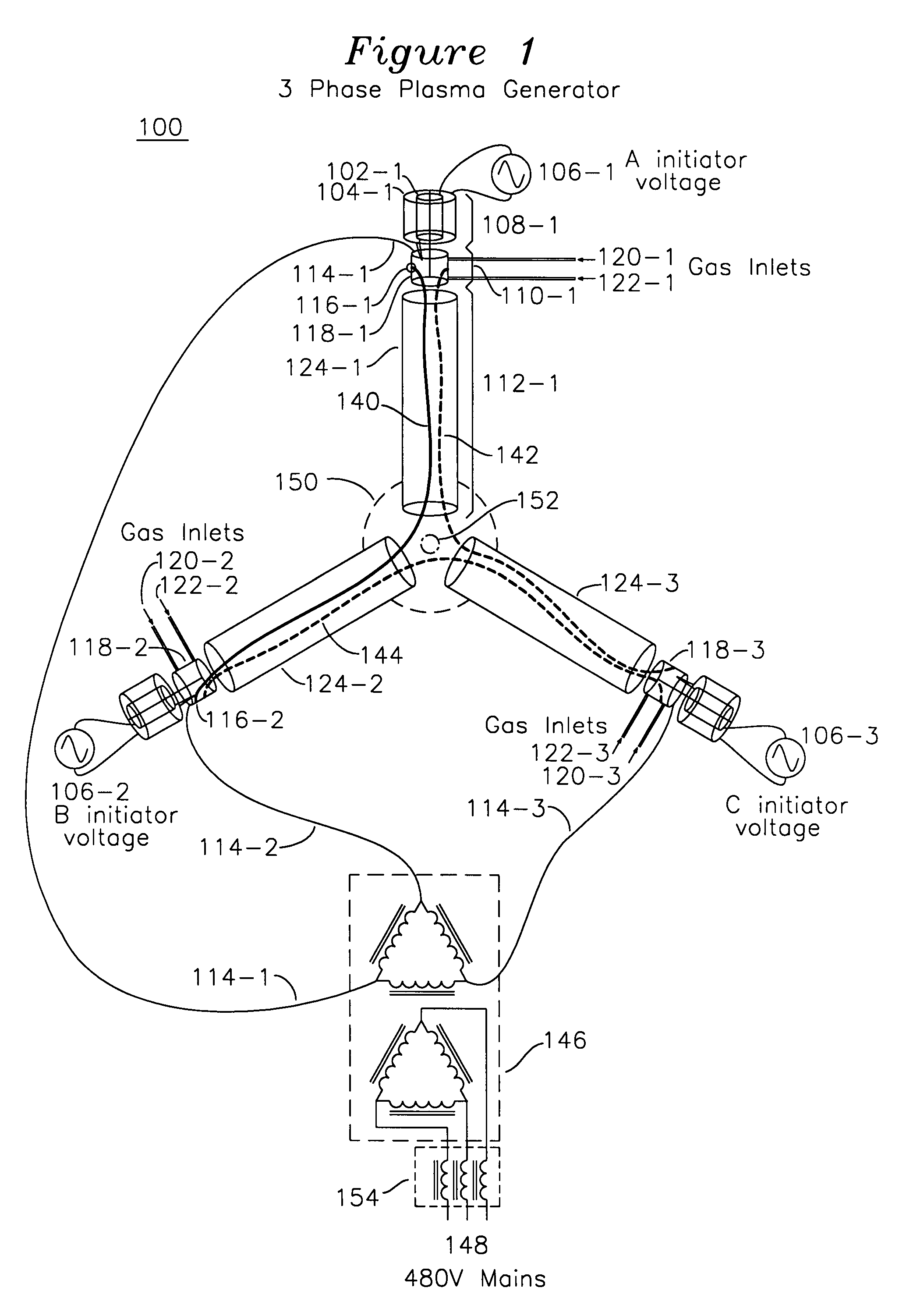
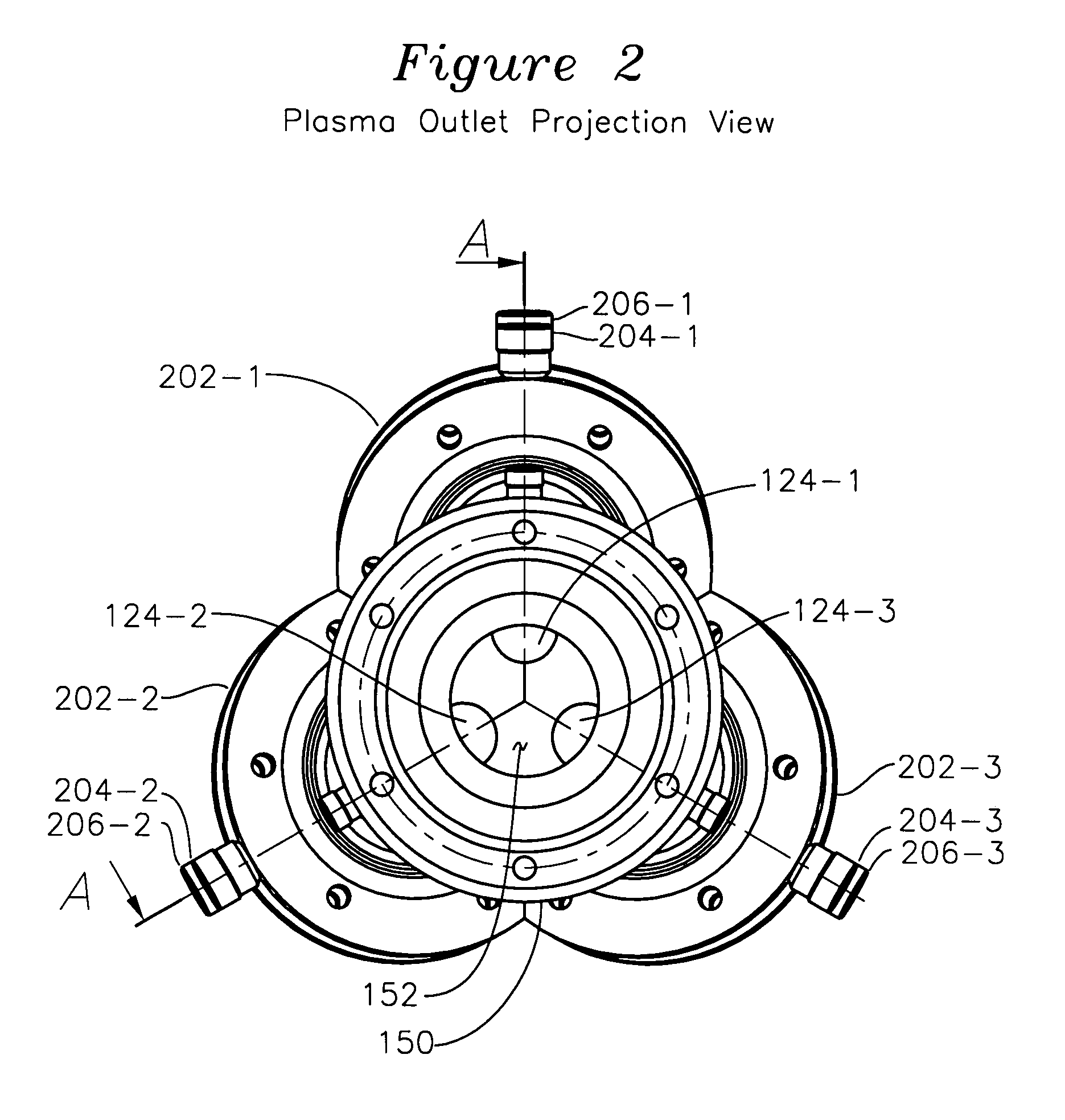
[0019]FIG. 1 shows a simplified projection view of a plasma generator 100, which comprises nozzle 150 having exit aperture 152 for the emission of plasma formed in a plurality of plasma tubes 124-1, 124-2, and 124-3. The individual elements are shown in an exploded view, however the plasma generator is a closed system whereby native gas enters at inlets 120-1, 122-1, etc., for each plasma source, and exits as a fully formed plasma at nozzle exit aperture 152. Each plasma tube such as 124-1 has an inner plasma channel for the passage of plasma through a plasma forming extent 112-1 with one end of the plasma channel attached to nozzle 150 and the other end attached to annular electrode 118-1, which in turn is coupled to one phase of the secondary winding of three phase transformer 146. The annular electrode 118-1 has an inner surface, optionally with a diameter in the range of 30 mm to 300 mm, and the region where a plasma interacts with the annular electrode inner surface is known as...


PUM


Abstract

A plasma generator for three phase mains alternating current operation has three plasma generation tubes interconnected with a nozzle, each plasma generation tube having a plasma initiator for forming a plasma into an electrode ring, the electrode ring including substantially tangential gas introduction orifices which cause gas entering the electrode ring to helically rotate. Each of the electrode rings is coupled to a unique one of the three phases of AC voltage supply, such that when the initiator plasma is introduced into one of the electrode rings, a plasma discharge occurs with a path from the electrode ring, through the plasma generation tube, and to a different electrode ring. Each electrode ring has gas introduced in a helically rotating manner such that the erosion of the surface of the electrode ring is uniform over the entire surface, and minimally erosive in a single arc attachment spot, since the arc spot is constantly moving as provided by the helical trajectory of the gas entering the electrode.

Description

FIELD OF THE INVENTION[0001]The present invention relates to the field of plasma gas generators, and particularly plasma gas generators continuously producing a source of plasma and operating on polyphase mains alternating current (AC).BACKGROUND OF THE INVENTION[0002]Plasma generators form high energy plasma gas, which is then used for a variety of application, including plasma-jet cutting, coatings, hard-facing, vitrification of radioactive materials, disinfection of waste, and many other applications. Industrial plasma generation systems may consume large amounts of power on the order of mega-watts (MW), and for these systems, it is desired that the plasma generator be simple and reliable. One problem of particular interest in high power plasma generation systems is extending the life of the electrode at the plasma-conductive interface. The plasma attachment region, known as the arc spot, of the electrode may preferentially erode compared to the other regions of the electrode, re...

Claims


Application Information

Patent Timeline
Patent Type & Authority Patents(United States)
IPC IPC(8): H05B31/26
CPCH05H1/44H05H1/36
Inventor RUTBERG, ALEXANDER P.RUTBERG, PHILIP G.SAFRONOV, ALEXEI A.SHIRYAEV, VASILY N.
Owner OAKS PLASMA
Why Eureka
Try Eureka