Measurement method using solar simulator

a simulator and measurement method technology, applied in the direction of optical radiation measurement, individual semiconductor device testing, instruments, etc., can solve the problems of large scale equipment, large time required until measurement, and irradiance tends to decreas

Inactive Publication Date: 2008-08-12
NISSHINBO IND INC
View PDF14 Cites 32 Cited by
  • Summary
  • Abstract
  • Description
  • Claims
  • Application Information

AI Technical Summary

Benefits of technology

[0027]By optimizing the flash pulse duration and the flash interval and measuring over a prescribed narrow irradiance range, it is possible to perform high-accuracy measurement.
[0042]Prior to the main measurement step involving controlling the load of the photovoltaic devices under measurement and measuring the current and the voltage, by carrying out a preliminary measurement operation of irradiating the photovoltaic devices under measurement with a flash from the light source and obtaining approximate values for the short-circuit current Isc, the open circuit voltage Voc and the maximum power Pmax which are the characteristics of the photovoltaic devices under measurement while sweeping the load of the photovoltaic devices, it is possible to control the load sweep speed to the characteristics of the photovoltaic devices under measurement so as to enable more efficient measurement.

Problems solved by technology

As a result, a very large scale equipment is required, which is impractical.
Moreover, unless lighting is continued under the same conditions the irradiance does not reach saturation, and therefore a great deal of time is required until measurement is started.
On the other hand, as the accumulated lighting time grows by long hours of lighting, the irradiance tends to decrease gradually, and thus the irradiance characteristics are not stable.
Thus, the irradiation time required for the devices under test depends on the operating speed of the shutter, and often exceeds several hundred milliseconds.
As the irradiation time lengthens the temperature of the photovoltaic devices itself rises, thus making accurate measurement difficult.
In addition, the parts inside the housing are constantly exposed to light, which causes the optical components (mirrors, optical filters, etc.) to deteriorate.
Further, once a fixed light source lamp is turned off and turned on again, it takes several tens of minutes for the irradiance to reach saturation.
As a result, however, the accumulated lighting time of such fixed light lamps adds up easily, resulting in a tendency for such lamps to reach the end of their useful lives relatively quickly.
Therefore, when using a fixed light-type solar simulator in a photovoltaic devices module production line, the number of lamps that burn out is added to the running cost, which increases not only the cost of measurement but also the cost of production.
In addition, with a fixed light solar simulator, the length of time during which light from the light source irradiates the photovoltaic devices under measurement is relatively long.
However, measurement of the temperature of the photovoltaic devices has the following problems and is not a simple matter.
Therefore, even when the photovoltaic devices cell accepts the light irradiated from the solar simulator and the temperature temporarily rises, it is extremely difficult to measure the temperature of the photovoltaic devices cell itself correctly.
This situation makes it difficult to measure the temperature of the photovoltaic devices cell accurately, and also makes it difficult to correct for the temperature correctly.
With either flash-based measurement method for measuring the current-voltage characteristics of photovoltaic devices, the problem of a rise in the temperature of the photovoltaic devices during measurement that arises in fixed light measurement methods is substantially nonexistent, and therefore errors caused by a temperature rise in the temperature of the photovoltaic devices cell do not arise easily.
However, it is known that the irradiance of a xenon lamp flash is uneven, and the flash must have an irradiance that is within a permissible range of ±5 percent.
The irradiance is then corrected for according to the irradiance during flash, but when the characteristics of the photovoltaic devices are unknown and the permissible range is large, measurement accuracy deteriorates.
As a result, if in the first generation of the flash the irradiance is insufficient and cannot be completely corrected, a long wait must be endured until the next generation of the flash.
In addition, in order to fire a long pulse the load of the lamp must be large, which in turn shortens the life of the lamp.
However, this type of short pulse flash measurement has the following problems. FIG. 6 is a diagram showing a waveform of a short pulse flash.
Further, when measuring a slow-response photovoltaic devices, the output response of the photovoltaic devices cannot track the irradiance waveform, which means that sometimes the measured output is lower than the true output.

Method used


Image

  • Measurement method using solar simulator
  • Measurement method using solar simulator
  • Measurement method using solar simulator

Examples


Embodiment Construction

[0050]Preferred embodiments of the present invention will now be described in detail, with reference to the accompanying drawings.

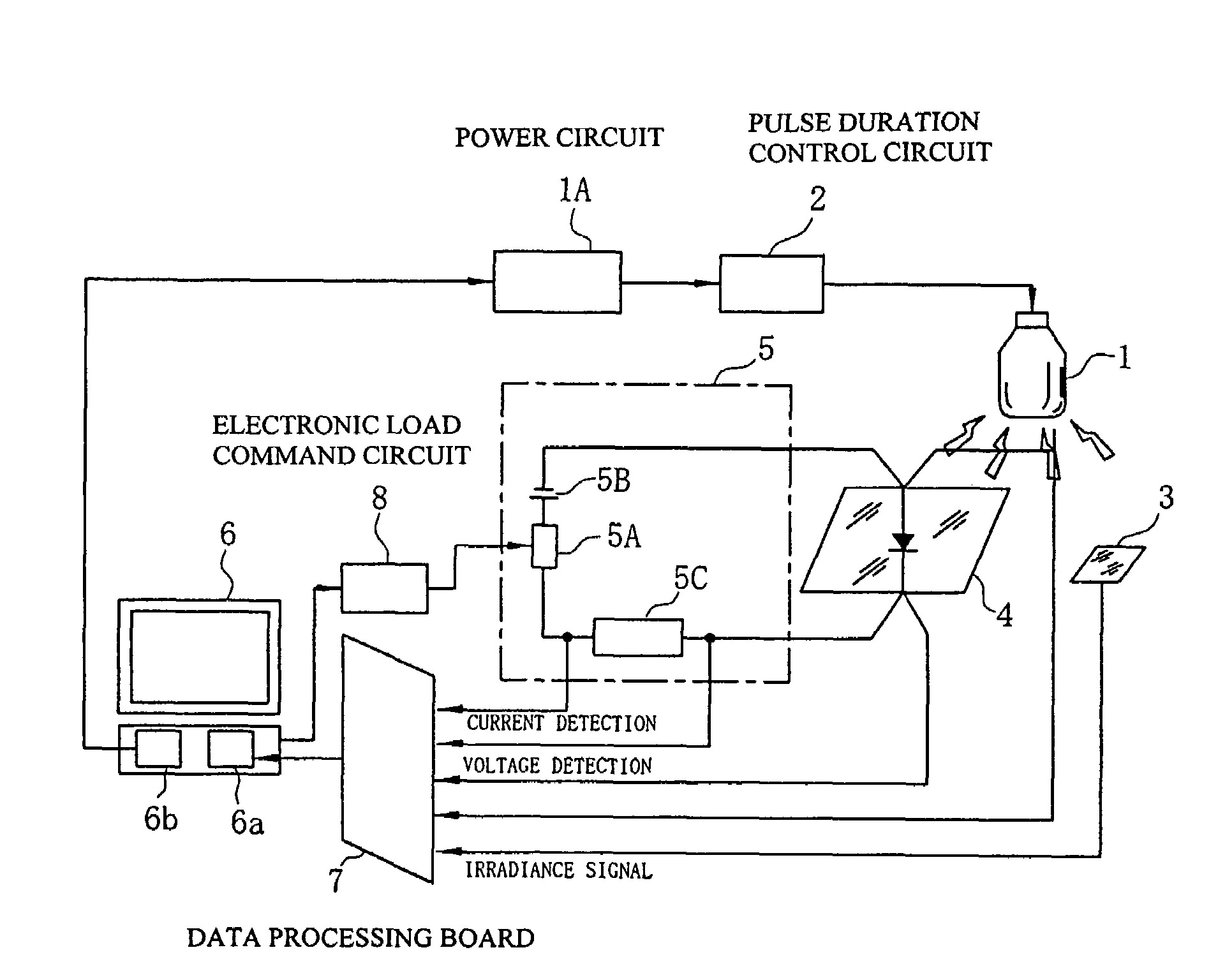
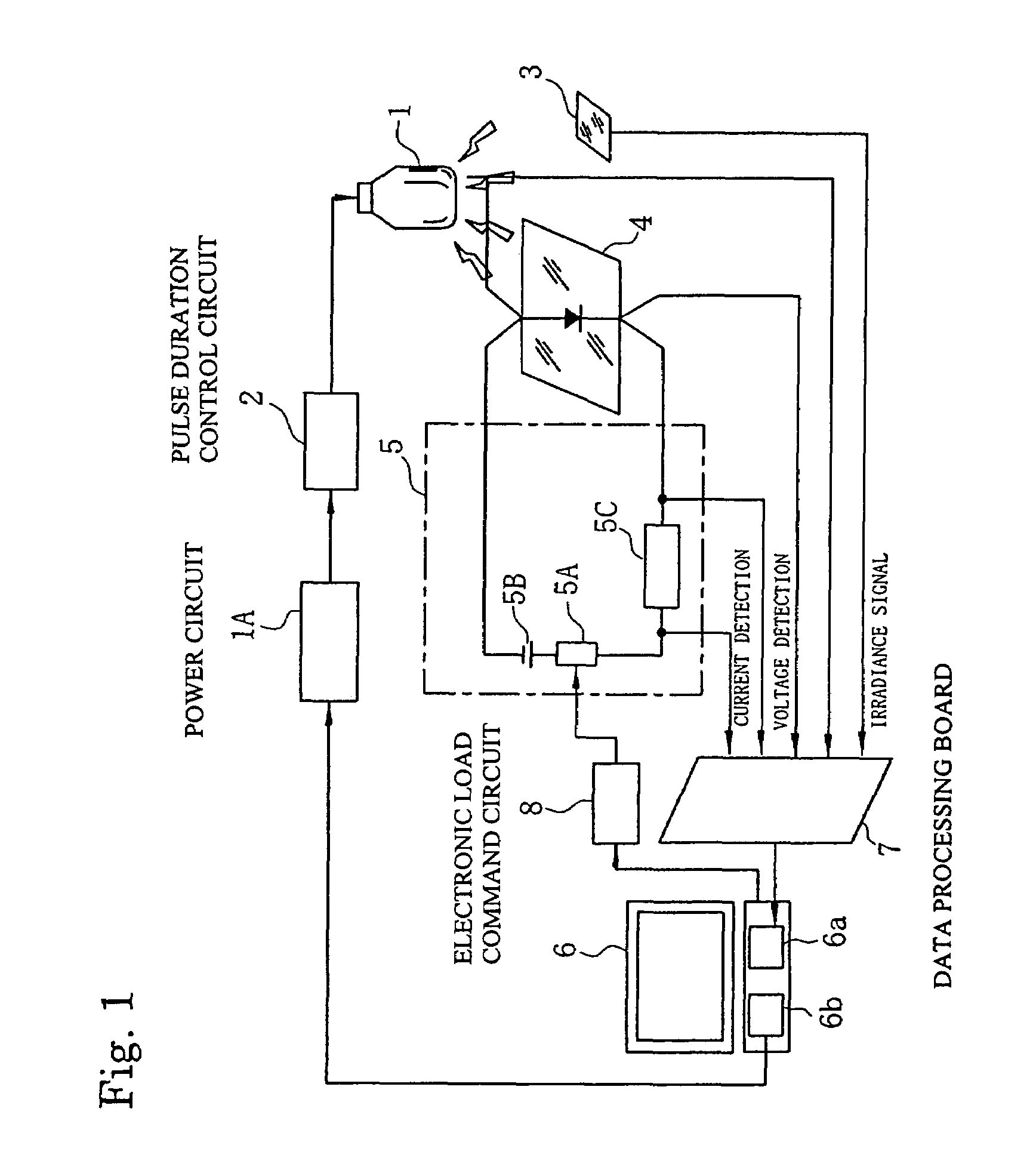
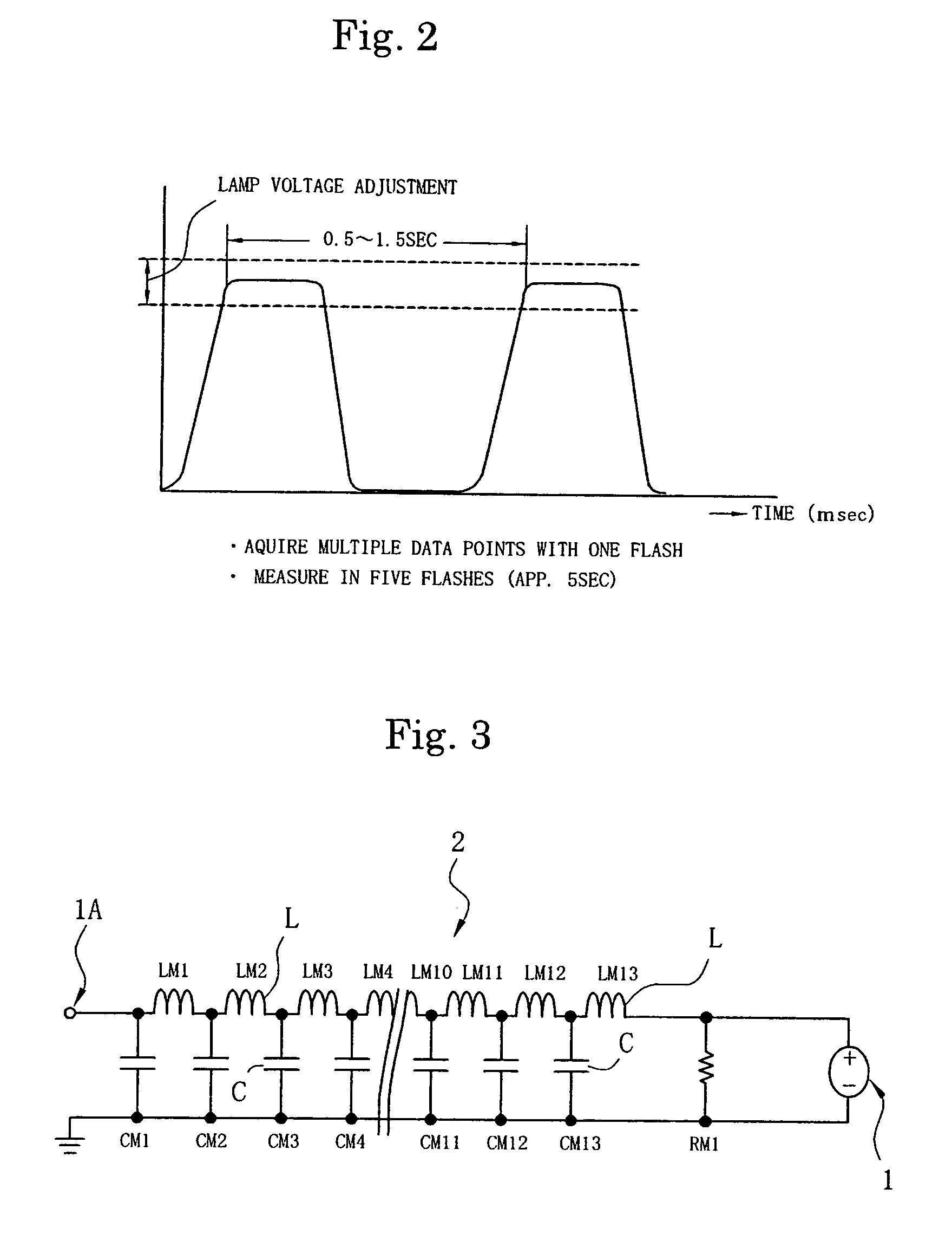
[0051]The present invention uses a middle flash, which has a pulse duration that is shorter than that of a single flash but longer than that of a short pulse flash. FIG. 1 is a block diagram showing one example of a solar simulator for implementing the measurement method of the present invention. FIG. 2 is a waveform diagram showing schematically an example of an irradiance waveform of a middle flash used in the measurement method of the present invention. FIG. 3 is a block diagram showing a pulse length control circuit, minus an intermediate part, using an LC circuit that generates a flash having a flattened part on the peak of the pulse waveform used in the present invention.

[0052]In the solar simulator shown in FIG. 1 employing the measurement method of the present invention, a pulse duration control circuit 2 (or a pulse duration delay circuit 2) usin...


PUM


Abstract

This invention provides a solar simulator measurement method capable of high-accuracy measurements with fast-response photovoltaic devices as well as with slow-response photovoltaic devices, and a solar simulator for implementing the method. A flash having a pulse waveform with a flattened peak is generated from a xenon lamp. The flash is sensed by an irradiance detector, its irradiance measured, and the irradiance of the light source is adjusted to fall within a prescribed narrow range based on the detected irradiance value. Then, the flash with irradiance within the prescribed range irradiates photovoltaic devices under measurement, and the current and the voltage output by the photovoltaic devices are measured at multiple points while a load of the photovoltaic devices is controlled. This process is repeated with multiple flashes to obtain an I-V curve for the photovoltaic devices.

Description

BACKGROUND OF THE INVENTION[0001]1. Field of the Invention[0002]The present invention relates to a measurement method using a solar simulator for high-speed, high-accuracy measurement of current-voltage characteristics (hereinafter also referred to simply as characteristics) of photovoltaic devices and the like and of photovoltaic devices panels.[0003]2. Background of the Invention[0004]The photoelectric conversion characteristics of photovoltaic devices, photo sensors and the like are measured by measuring the current-voltage characteristics of the photovoltaic devices under irradiance. In the measurement of the characteristics of photovoltaic devices, a graph is set up with voltage on the horizontal axis and current on the vertical axis and the acquired data is plotted to obtain a current-voltage characteristics curve. This curve is generally called an I-V curve.[0005]As the measurement methods, there are methods that use sunlight as the irradiating light and methods that use an a...

Claims


Application Information

Patent Timeline
Patent Type & Authority Patents(United States)
IPC IPC(8): G01R31/302
CPCG01J1/08H02S50/10G01J1/32Y02E10/50
Inventor SHIMOTOMAI, MITSUHIROSHINOHARA, YOSHIHIRO
Owner NISSHINBO IND INC
Why Eureka
Try Eureka