Working control device

a technology of working control and control device, which is applied in the direction of electric controllers, total factory control, program control, etc., can solve the problems of time-consuming education and training of the operator who creates the nc data, repeating the same failure between different operators, etc., and achieve the effect of preventing similar failures

Inactive Publication Date: 2008-08-12
FUJITSU LTD
View PDF36 Cites 8 Cited by
  • Summary
  • Abstract
  • Description
  • Claims
  • Application Information

AI Technical Summary

Benefits of technology

[0021]A contrivance of the invention is, putting an emphasis on similarities of a working tool, a working process, further, a behavior of a cutting tool during the working and a result of the working if there are similarities in configuration between design data of the object workpiece that should be worked and the working cases conducted in the past, that the working case is accumulated and searched out based on characteristics of the configuration, and the working conditions are determined based on this working case, whereby a result of the working in the past can be utilized. Namely, even a less-experienced operator can perform the working based on the past examples accumulated on a database. Moreover, failure cases can be accumulated together with successful cases after the cutting / working, and it is therefore possible to prevent similar failures from being repeated.

Problems solved by technology

(a) Know-how of the well-experienced operator who creates the NC data can not be reflected in cutting conditions by other operators, and therefore the same failure is to be repeated between different operators.
(b) Education and training of the operator who creates the NC data is time-consuming.

Method used


Image

  • Working control device
  • Working control device
  • Working control device

Examples


Embodiment Construction

[0066]A working system will be explained based on drawings in FIGS. 1 through 35 by way of embodiments of the invention.

[0067]

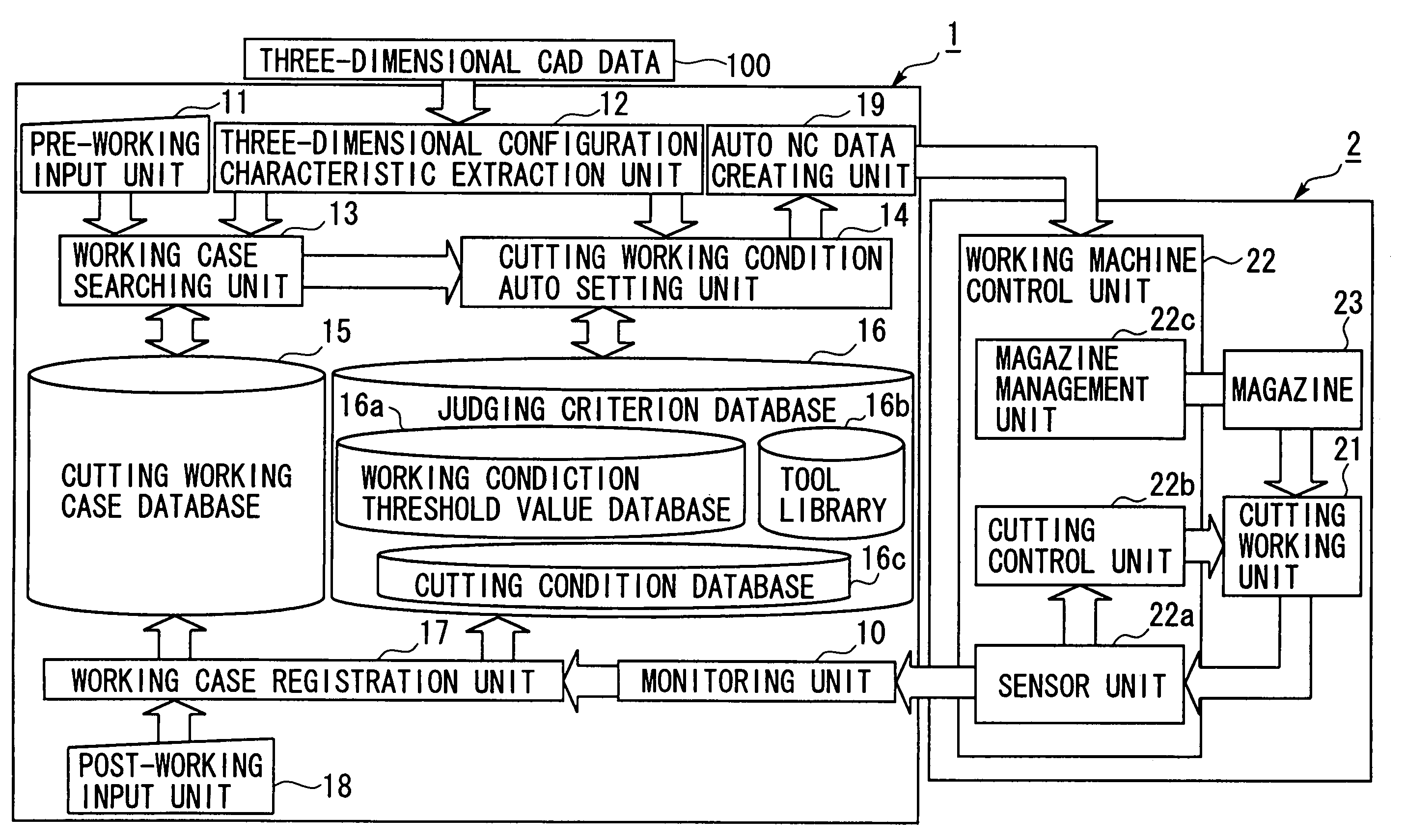
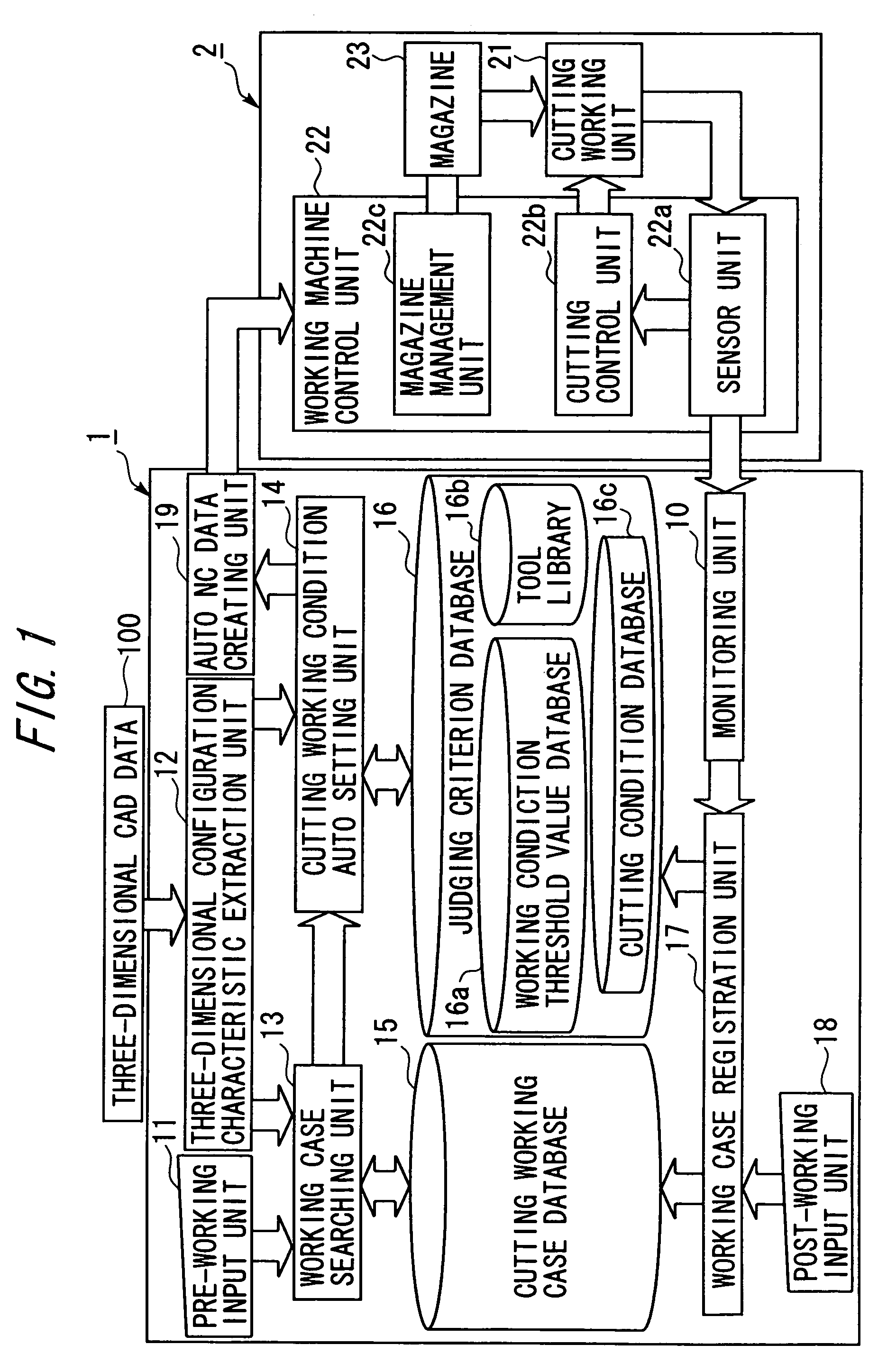
[0068]FIG. 1 is a block diagram showing an architecture of the working system in an embodiment.

[0069]The working system in the embodiment is constructed of a working control device 1 and a working machine 2 controlled by this working control device 1.

[0070]§1. Working Control Device

[0071]The working control device 1 includes a pre-working input unit 11, a three-dimensional configuration characteristic extraction unit (corresponding to a configuration characteristic extraction unit) 12, a case searching unit 13, a cutting working condition auto setting unit (corresponding to a working condition setting unit) 14, a cutting working case database (corresponding to a working case storage unit) 15, a judgment criterion database (corresponding to a judgment criterion storage unit) 16, a working case registration unit 17, a post-working input unit 18, an auto NC data...


PUM


Abstract

To provide a working control device, a working control program and a working control system enabling the working under proper working conditions by searching for a working case corresponding to characteristics of a configuration to be worked and setting the working conditions based on this working case. Configuration information about characteristics of a three-dimensional configuration is obtained from design data of an object workpiece, a working case is searched out based on the configuration information from the working case storage unit storing working conditions, as a working case, of the working conducted in the past, the working conditions are determined based on the working case searched out by the case searching unit, and a working machine is controlled based on the working conditions.

Description

BACKGROUND OF THE INVENTION[0001]The invention relates to a technology of obtaining an object workpiece by working a work material in a way that controls a cutting machine on the basis of design information defined on a computer.[0002]There has hitherto been known a device contrived to automatically perform working by controlling a working machine on the basis of CAD data, etc. For instance, there is proposed a control device for a machine tool that includes tool route determining means for: inputting workpiece data about workpiece configuration data concerning a final workpiece configuration and workpiece data about a material and a configuration of the workpiece; generating a workpiece working tool route on the basis of data stored with machine s data containing characteristics of a machine body such as a column, a bed, etc. of the machine tool, and tool s data about a working tool which contain a deformation, etc. at a working time when this tool is attached to a holder; and dete...

Claims


Application Information

Patent Timeline
Patent Type & Authority Patents(United States)
IPC IPC(8): G06F19/00G05B11/01B23Q15/00G05B19/4093G05B19/4097
CPCG05B19/40937G05B19/40938G05B19/4097G05B2219/35084G05B2219/35529G05B2219/49086G05B2219/36284G05B2219/36289G05B2219/36296G05B2219/36352G05B2219/36357G05B2219/35531Y02P90/02
Inventor YAMAGUCHI, SHINGOTAKAHASHI, HIROSHIKANBAYASHI, SATOSHIKURITA, KATSUYUKI
Owner FUJITSU LTD
Why Eureka
Try Eureka