Pipette system and pipette array

a pipette array and pipette technology, which is applied in the direction of liquid dispensing, capacity measurement calibration, containers, etc., can solve the problems of limited pipette precision, inability to install 96 syringe pumps, and inability to pipette a small volume at a high precision

Inactive Publication Date: 2008-08-19
FRAUNHOFER GESELLSCHAFT ZUR FOERDERUNG DER ANGEWANDTEN FORSCHUNG EV
View PDF25 Cites 36 Cited by
  • Summary
  • Abstract
  • Description
  • Claims
  • Application Information

AI Technical Summary

Benefits of technology

[0007]The present invention is based on the problem of providing a pipette system that avoids the disadvantages in prior art and allows particularly for the precise control of each individual pipette within a pipette array consisting of inventive pipette systems.

Problems solved by technology

The installation of 96 syringe pumps is not possible for reasons of space and costs.
In view of the size of the air cushion between the plunger and the samples, the minimum volume that can be pipetted with a high precision is limited to the micro litre range.
The pipetting precision remains comparatively low, which restricts the application to tests of a predominantly qualitative nature.

Method used


Image

  • Pipette system and pipette array
  • Pipette system and pipette array
  • Pipette system and pipette array

Examples


Embodiment Construction

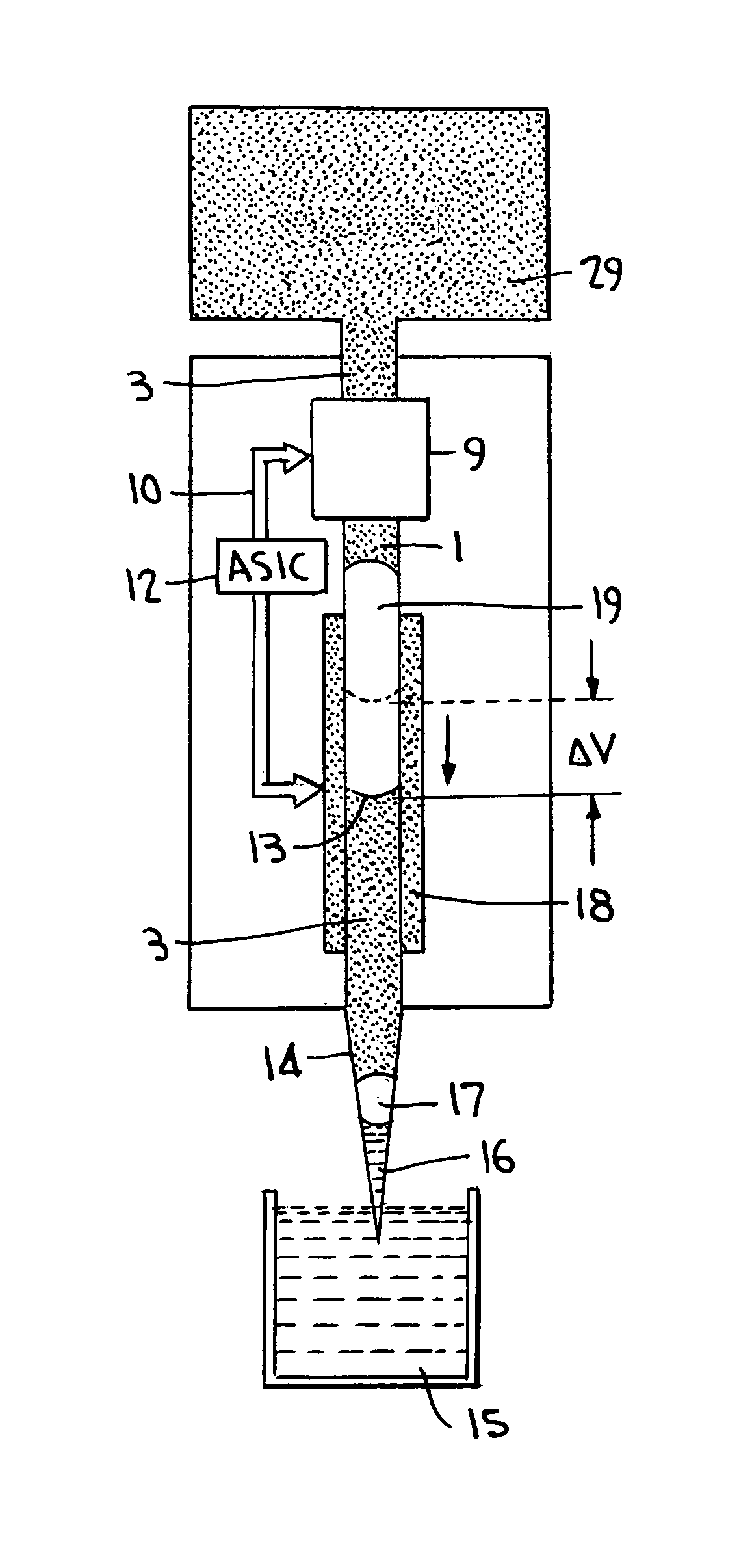
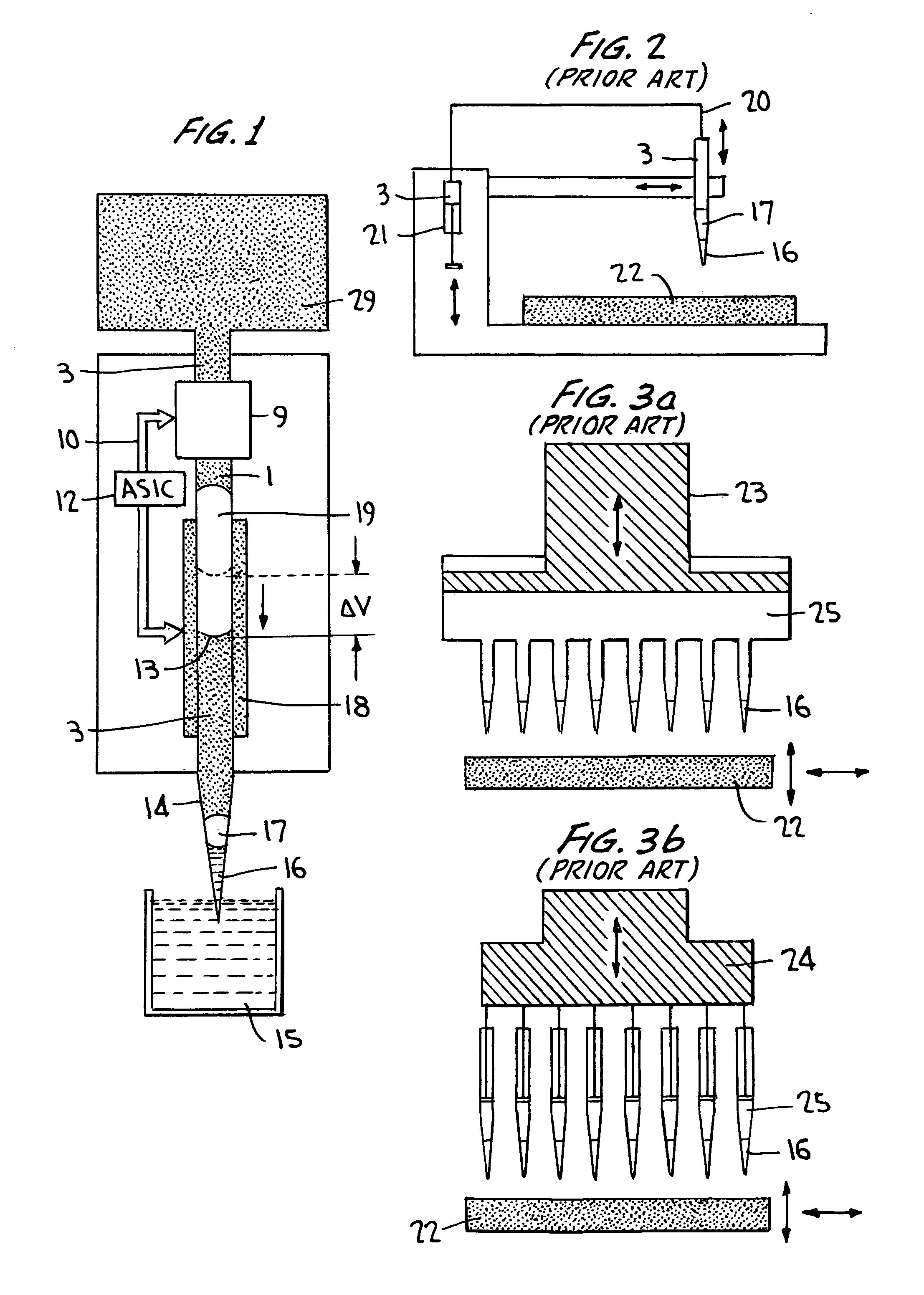
[0026]FIG. 1 is a schematic view of the structure of a controllable pipette with the inventive pipette system. The pipette is provided with a filling level sensor (18) inside a capillary tube (1). The filling level sensor consists of a chip mounted laterally along the longitudinal direction, which is capable of continuously monitoring the position of a phase boundary (13) inside the capillary tube, preferably between air and a liquid. In the case where the filling level sensor is designed as sensor element in correspondence with the German Patent Application DE 199 44 331, the chip contains micro-structured metal electrodes whose active zones are located inside the capillary tube. They are distributed over the entire length of the chip, with a certain arrangement—that will also be referred to as “meander” in the following—being continuously repeated. An actuator (9), which is capable of taking an active influence on a current flowing through the capillary tube, is provided on the up...


PUM

PropertyMeasurementUnit
lengthaaaaaaaaaa
phaseaaaaaaaaaa
electrically conductiveaaaaaaaaaa

Abstract

A pipette system including a pipette capillary tube and an actuator, with the actuator serving to set the position of a phase boundary between a system medium and a second medium in the pipette capillary is described. A sensor element is also provided for measuring the position of the phase boundary, in such a way that the actuator is controlled by a regulating element in response to an output signal from the sensor element.

Description

FIELD OF INVENTION[0001]The present invention relates to a pipette system and to pipette arrays of pipette systems, comprising a control loop consisting of an actuator, a regulating element and a sensor element for controlling the pipetting operation.[0002]The inventive pipette systems and pipette array is suitable for pipetting liquids in HTS (high throughput screening), in clinical chemistry and in chemical synthesis with particular advantages.[0003]There are many applications, e.g. in clinical chemistry, where different volumes must be pipetted in parallel with a high precision (3% coefficient of variation in typical cases). At the same time, it is necessary to keep the minimum sample volumes as small as possible in order to minimise the consumption of reagents or in order to allow for an increasing packing density of the micro titre plates. To this end, it should be possible to transfer volumes in the sub-micro litre range by means of an array of actively controlled, individuall...

Claims


Application Information

Patent Timeline
Patent Type & Authority Patents(United States)
IPC IPC(8): B01L3/02G01F11/06G01F11/28G01F23/24G01N1/00G01N35/10
CPCB01L3/022B01L3/0241G01F11/284G01F23/242G01N35/10B01L2200/143B01L2300/0838B01L2400/0442Y10T436/2575B01L2400/0487B01L2400/046
Inventor LISEC, THOMASMUHLMANN, SASCHAGRUNZIG, SVEN
Owner FRAUNHOFER GESELLSCHAFT ZUR FOERDERUNG DER ANGEWANDTEN FORSCHUNG EV
Why Eureka
Try Eureka