Camera and camera system capable of changing gain value and exposure time

Inactive Publication Date: 2008-08-19
CANON KK
View PDF20 Cites 36 Cited by
  • Summary
  • Abstract
  • Description
  • Claims
  • Application Information

AI Technical Summary

Benefits of technology

[0014]An object of the invention is to provide a camera and a camera system which improves the S/N ratio of the image-t

Problems solved by technology

However, in a digital still camera, if the shutter speed is increased to prevent image blur and the image-taking sensitivity is r

Method used


Image

  • Camera and camera system capable of changing gain value and exposure time
  • Camera and camera system capable of changing gain value and exposure time
  • Camera and camera system capable of changing gain value and exposure time

Examples


embodiment 1

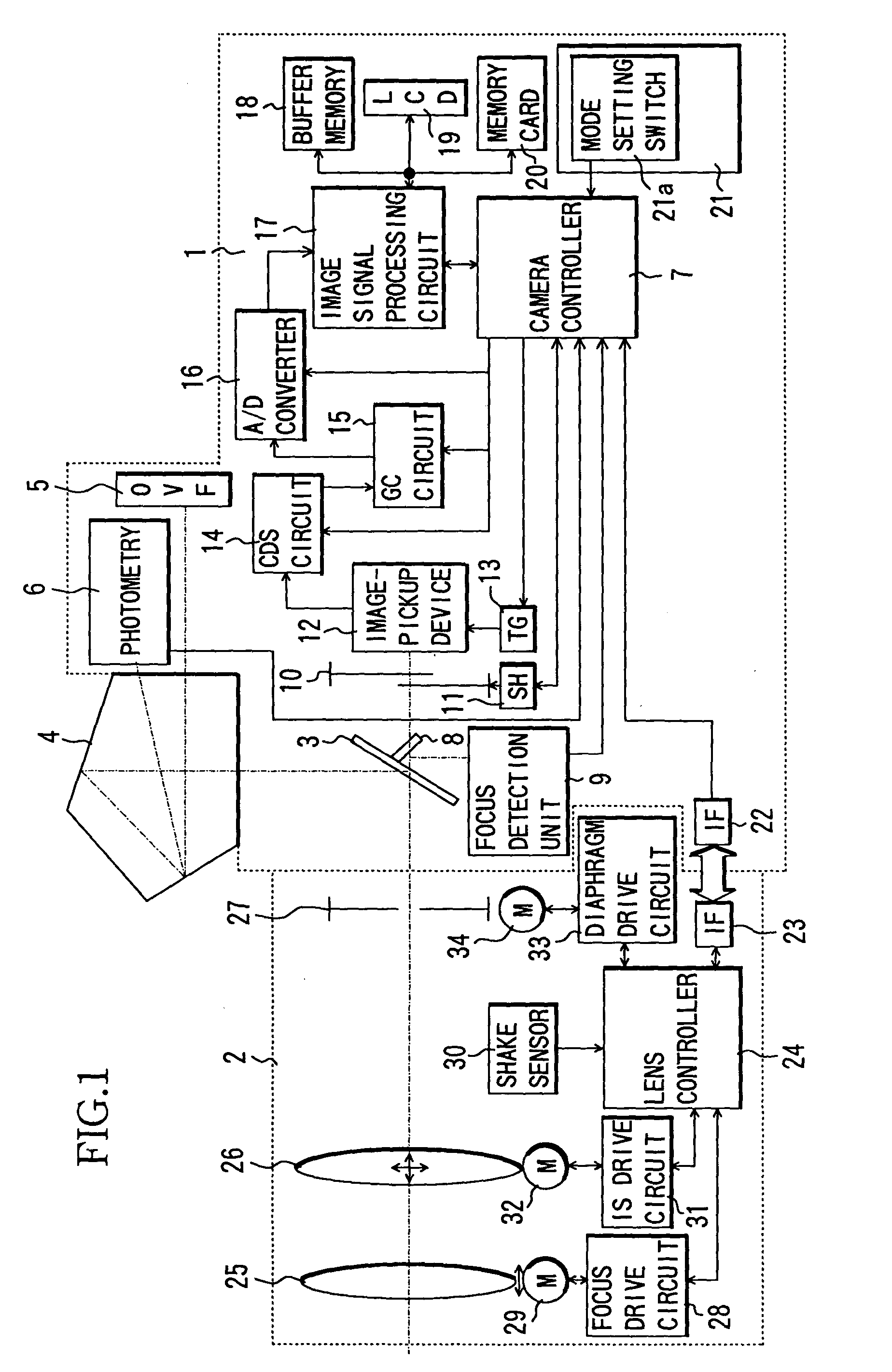
[0029]FIG. 1 shows a camera system comprising a camera 1 which is a single-lens reflex digital still camera, and an interchangeable lens (lens apparatus) 2 which is attachable to the camera 1.

[0030]An image-taking light flux from an object passes through an image-taking optical system inside the interchangeable lens 2 and enters the inside of the camera 1. A part of this image-taking light flux is reflected by a quick-return main mirror 3 whose central portion is formed as a half mirror, and then the image thereof is formed on an unillustrated focusing plate. The object image formed on the focusing plate is converted to be an erect image by a pentaprism 4 and observed by a camera operator (not shown) through an optical finder 5.

[0031]In the camera 1, a photometric circuit 6 measures the luminance of the object image on the focusing plate and inputs the measurement results into a camera controller (control circuit) 7. A photometric sensor inside the photometric circuit 6 is divided i...

embodiment 2

[0109]In the abovementioned Embodiment 1, a case where the sensitivity of the image-pickup device and the shutter speed are changed in accordance with the on / off condition of the IS function and the luminance difference between the luminance of a main object and the maximum luminance of other areas is described, however, the sensitivity of the image-pickup device and the shutter speed may be changed further in accordance with a detected amplitude of shake.

[0110]The structure of a camera system to which this embodiment is applied is the same as that of Embodiment 1, and common components are attached with the same symbols as those in Embodiment 1 and description thereof is omitted.

[0111]With reference to the flowchart of FIG. 7, operations of the camera 1 side in this embodiment are described. In FIG. 7, portions with circled alphabetic letters of FIG. 7 are related to portions with the same circled alphabetic letters of FIG. 3. Furthermore, herein, Steps 500 through 506 that are mai...

embodiment 3

[0125]In the abovementioned Embodiment 1, a case where the sensitivity of the image-pickup device and the shutter speed are changed in accordance with the on / off condition of the IS function and the luminance difference between the luminance of the main object and the maximum luminance of other areas is described, however, it is also possible that the sensitivity of the image-pickup device and the shutter speed are changed in accordance with the image-taking mode.

[0126]The structure of a camera system to which this embodiment is applied is the same as that of Embodiment 1, and common components are attached with the same symbols as those in Embodiment 1 and description thereof is omitted.

[0127]With reference to the flowchart of FIG. 8, operations of the camera 1 side of this embodiment are described. In FIG. 8, portions with circled alphabetic letters are related to portions with the same circled alphabetic letters of FIG. 3. Herein, Steps 600 through 606 that are main operations ar...


PUM


Abstract

An image-pickup apparatus which improves the S/N ratio of an image-pickup system, prevents image blur and saturation of signals from an image-pickup device, and enables taking an excellent image, is disclosed. The camera of the invention which takes images through an image-taking optical system having a shake correction unit which drives a part of an image-taking optical system to correct image blur caused by camera shake and includes an image-pickup device which photoelectrically converts an object image formed by the image-taking optical system and a control circuit which controls operations of the camera, wherein the control circuit changes the sensitivity and the exposure time of the image-pickup device whether the shake correction unit is in operation or not.

Description

BACKGROUND OF THE INVENTION [0001]1. Field of the Invention[0002]The present invention relates to a digital still camera having an image blur correcting function.[0003]2. Description of Related Art[0004]In a silver-salt film camera, its image-taking sensitivity (ISO sensitivity) cannot be changed unless a loaded film is replaced, however, in a digital still camera, its image-taking sensitivity can be easily changed by changing the gain of signals from an image pickup device such as a CCD.[0005]Therefore, an image-taking sensitivity suitable for image-taking conditions can be set by a camera operator or at the camera side. For example, when it is desired to reduce affects from image blur by increasing the shutter speed, the image-taking sensitivity is set to be higher in accordance with the shutter speed increase.[0006]Furthermore, as an image blur prevention system, a system which optically prevents image blur by moving a part of the lenses of the image-taking optical system has bee...

Claims


Application Information

Patent Timeline
IPC IPC(8): H04N5/228H04N5/235H04N5/238G03B7/091G03B5/00G03B7/28G03B17/14H04N5/232H04N101/00
CPCH04N5/23209H04N5/23212H04N5/2352H04N5/23258H04N5/23287H04N5/23248H04N23/663H04N23/672H04N23/68H04N23/6812H04N23/687H04N23/72
Inventor IMADA, SHINJI
Owner CANON KK
Why Eureka
Try Eureka