
TMR/GMR amplifier with input current compensation

a technology of input current and compensation, applied in the field of amplifiers, can solve problems such as the difficulty of designing the overall frequency response of the circui

Active Publication Date: 2008-08-19
MARVELL ASIA PTE LTD
View PDF13 Cites 6 Cited by
  • Summary
  • Abstract
  • Description
  • Claims
  • Application Information

AI Technical Summary

Benefits of technology

The solution effectively cancels feedback error currents, stabilizes the bias current, and simplifies the frequency response, enhancing the performance of the amplifier system without increasing recovery time from sleep mode.

Problems solved by technology

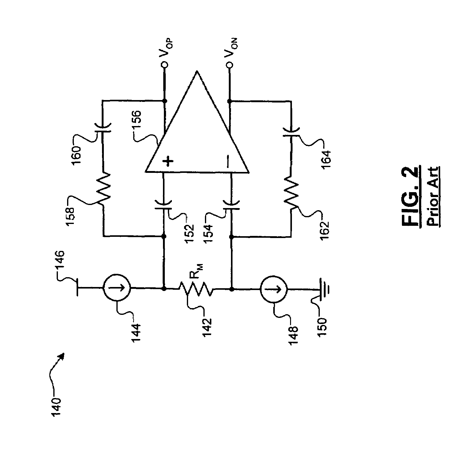
However, the third and fourth capacitances 160 and 164 create low-pass filters that interact with the high-pass filters created by the first and second capacitances 152 and 154, making the overall frequency response of the circuit difficult to design.

Method used


Image

  • TMR/GMR amplifier with input current compensation
  • TMR/GMR amplifier with input current compensation
  • TMR/GMR amplifier with input current compensation

Examples


Embodiment Construction

[0025]The following description of the preferred embodiments is merely exemplary in nature and is in no way intended to limit the invention, its application, or uses. For purposes of clarity, the same reference numbers will be used in the drawings to identify similar elements. As used herein, the term module refers to an application specific integrated circuit (ASIC), an electronic circuit, a processor (shared, dedicated, or group) and memory that execute one or more software or firmware programs, a combinational logic circuit, and / or other suitable components that provide the described functionality.

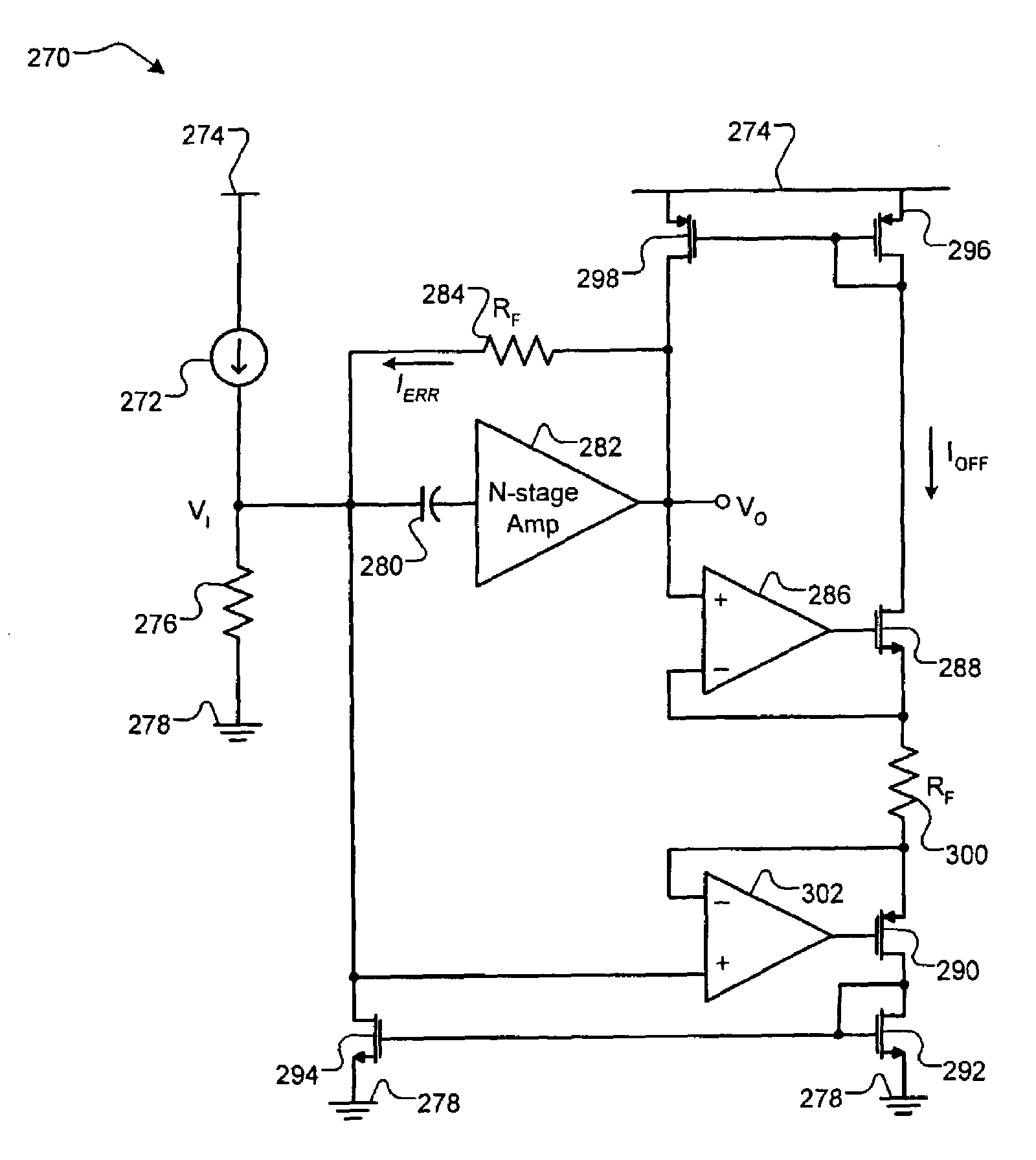
[0026]Referring now to FIG. 3, a block diagram of an exemplary amplifier 200 incorporating a feedback error current cancellation system is depicted. An input device 202 communicates a signal to an input of an amplifier 204. The input of the amplifier 204 also communicates with a first terminal of a feedback network 206 and a first terminal of a feedback current cancellation module 208. ...


PUM

PropertyMeasurementUnit
lengthaaaaaaaaaa
currentaaaaaaaaaa
resistanceaaaaaaaaaa

Abstract

An amplifier system with feedback current cancellation comprises an amplifier with an input, an output, and at least one stage. A feedback network communicates with the input and output of the amplifier. A feedback current cancellation module that provides a first current at the input of the amplifier that substantially cancels a second current provided at the input of the amplifier by the feedback network.

Description

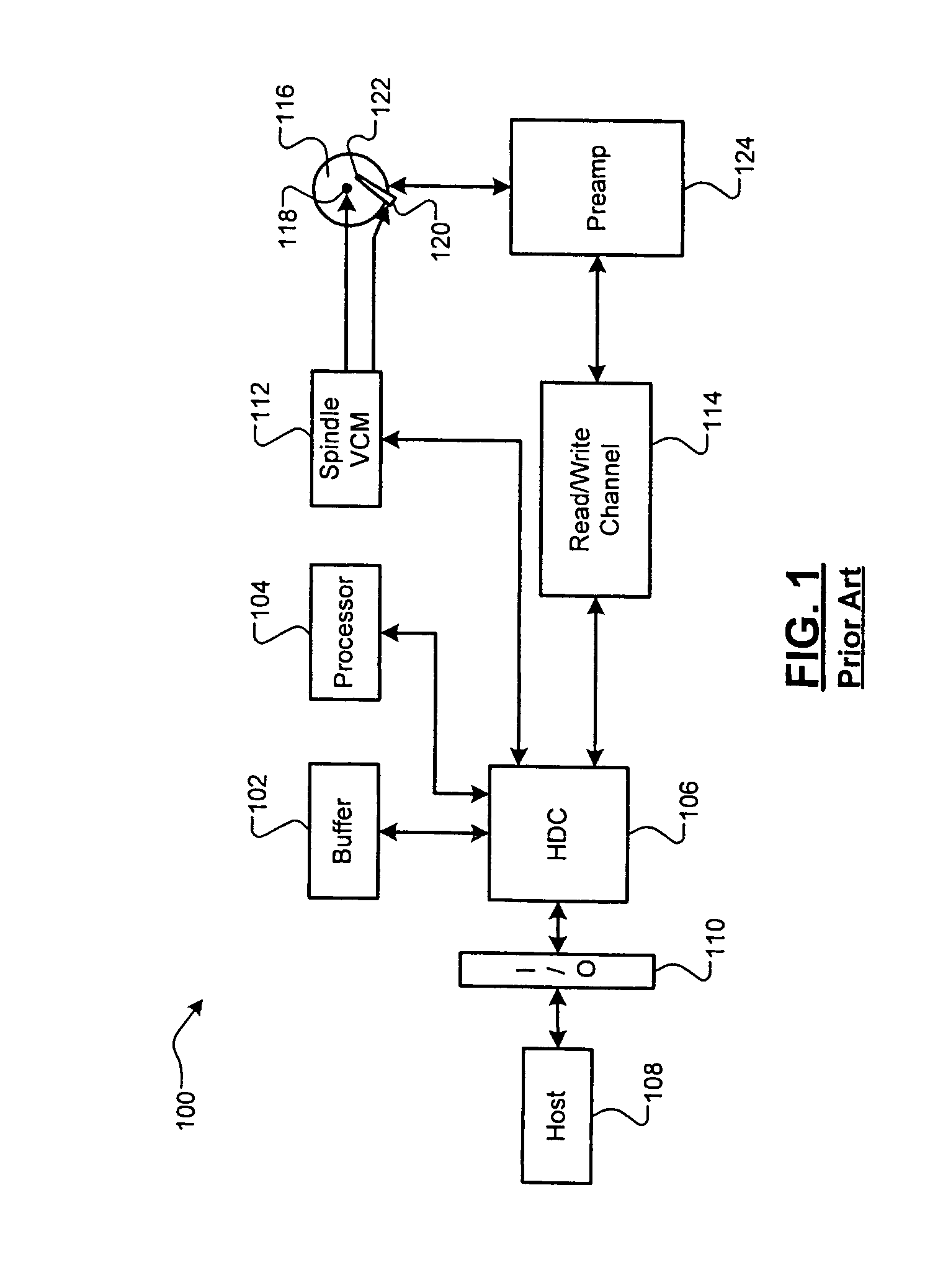
FIELD OF THE INVENTION[0001]The present invention relates to amplifiers, and more particularly to feedback error current cancellation in a closed-loop amplifier.BACKGROUND OF THE INVENTION[0002]Referring to FIG. 1, an exemplary magnetic storage system 100 such as a hard disk drive is shown. A buffer 102 stores data that is associated with control of the hard disk drive. The buffer 102 may employ SDRAM or other types of low latency memory. A processor 104 performs processing that is related to the operation of the hard disk drive. A hard disk controller (HDC) 106 communicates with the buffer 102, the processor 104, a host 108 via an I / O channel 110, a spindle / voice coil motor (VCM) driver 112, and a read / write channel circuit 114.[0003]During a write operation, the read / write channel circuit 114 encodes the data to be written onto the storage medium. The read / write channel circuit 114 processes the signal for reliability and may include, for example, error checking and correcting cod...

Claims


Application Information

Patent Timeline
Patent Type & Authority Patents(United States)
IPC IPC(8): G11B5/09G11B5/02H03F15/00
CPCG11B5/02H03F1/342H03F3/45475G11B2005/0018H03F2203/45528H03F2200/453H03F2200/474H03F2203/45136H03F2200/144
Inventor VOO, THART FAH
Owner MARVELL ASIA PTE LTD
Learn More