Speed limiting turbine for rotary driven sprinkler

a technology of speed limit turbine and rotary drive, which is applied in the direction of burners, combustion types, combustion processes, etc., can solve the problems of premature failure of gear driven sprinklers, damage to sprinklers, and plastic housing material seiz

Inactive Publication Date: 2008-08-26
KAH JR CARL L
View PDF19 Cites 4 Cited by
  • Summary
  • Abstract
  • Description
  • Claims
  • Application Information

AI Technical Summary

Benefits of technology

[0007]It is accordingly the primary object of this invention to provide a turbine-driven sprinkler which incorporates a speed limiting mechanism which protects the turbine from damage when compressed air is used to blow out the system in preparation for winter, but still permits satisfactory operation when the turbine is water-driven.

Problems solved by technology

This can be very damaging to the sprinklers which have water turbines which are normally water powered and rotate at a much slower speed with the water which is a relatively heavy incompressible fluid and does not generate the high turbine stator velocities produced when air, an expandable relatively light fluid, is expanded across the turbine stator onto the turbine blades.
The high turbine shaft velocities can heat the shaft and cause it to seize to the plastic housing material.
This prevents the turbine from turning and renders it unusable in the future unless care is taken to limit the system air, blow-out time and pressures.
This has proved to be one of the major causes for premature failure of gear driven sprinkler in colder climates, where sprinklers are used for only part of the year, and should last much longer than in warmer climates where they are run year round.
This design, however, can not effectively limit rotational speed when the turbine is driven by a compressible fluid such as air, and still allow the turbine to run at a sufficiently high speed when it is driven by an incompressible fluid such as water because of the rapid expansion of the compressed air as it enters the turbine chamber.
Other turbine speed limiting mechanisms are known, but to applicant's knowledge, none of these are suitable for turbines which must run on both compressible and incompressible fluids.

Method used


Image

  • Speed limiting turbine for rotary driven sprinkler
  • Speed limiting turbine for rotary driven sprinkler
  • Speed limiting turbine for rotary driven sprinkler

Examples


Embodiment Construction

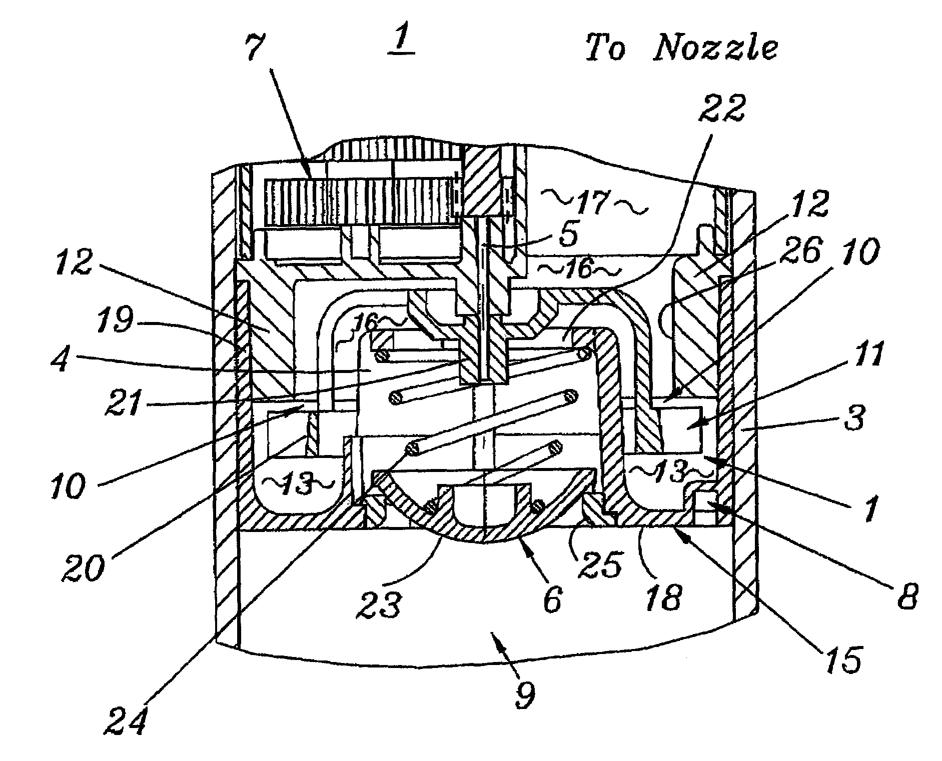
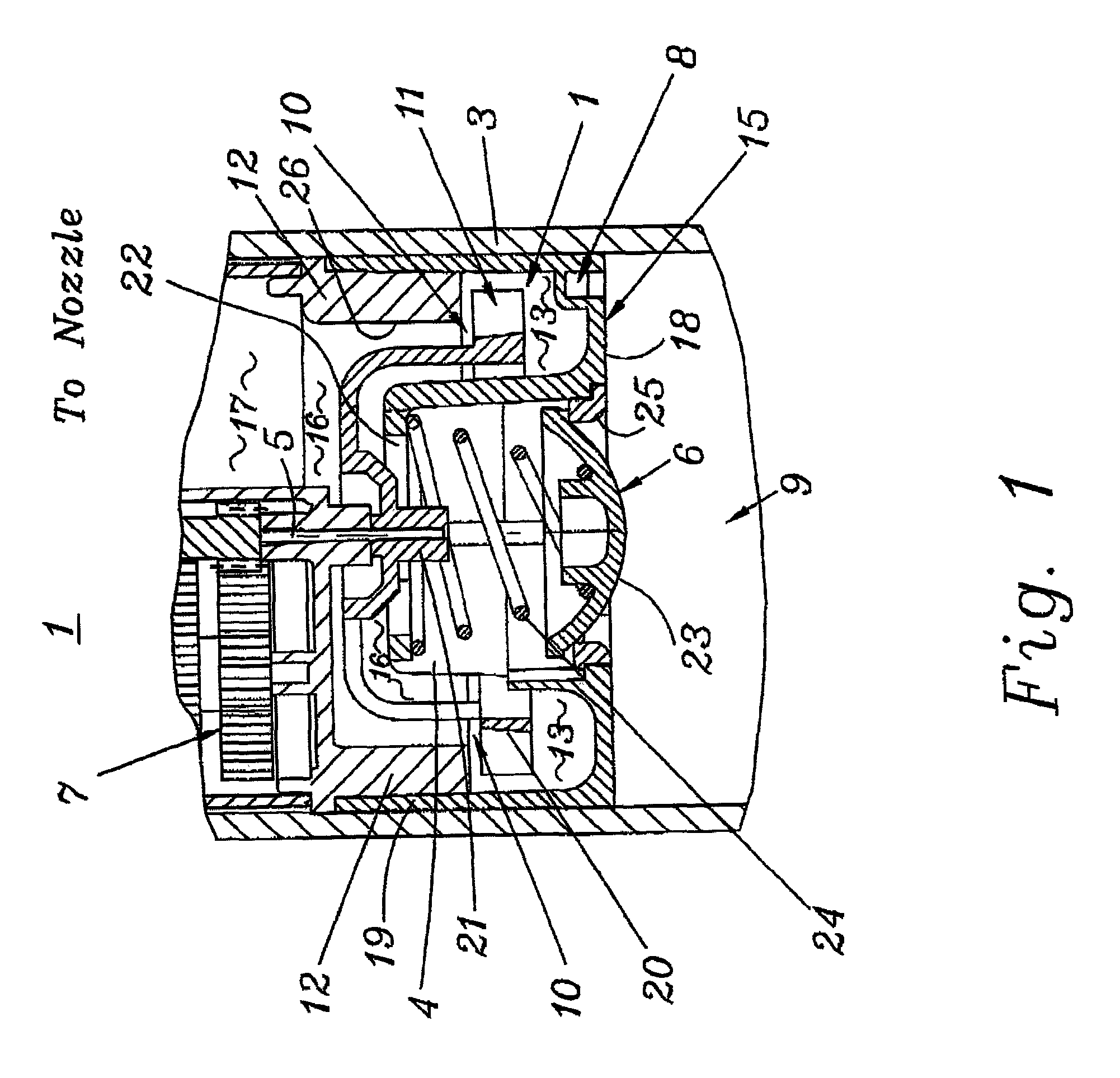
[0016]FIG. 1 shows in cross-section, the turbine assembly, generally denoted at 1, of a water turbine driven sprinkler such as described in detail in my U.S. Pat. No. Re 35,037, the disclosure of which is incorporated herein by reference as if fully set forth. The turbine assembly 1 is mounted in a housing 3, and, by way of an output shaft 5, drives a gear box 7 which rotates or oscillates a sprinkler head (not shown). As will be understood, water (or during winterization, compressed air) entering turbine assembly 1 from below at 9 drives the turbine, and thereafter flows through an outlet passage 17 to the sprinkler head.

[0017]The turbine itself is comprised of a rotor 11 located in a rotor chamber 13 formed by a stator cover assembly 15 positioned on the upstream side of the turbine, and a lower cover 12 for gearbox 7. Stator cover assembly 15 is in the form of an inverted cup with a central portion 4 that houses a flow by-pass valve sub-assembly 6 described below. Extending radia...


PUM


Abstract

A speed limiting mechanisms for turbine-driven fluid distribution apparatus usable with compressible fluid such as compressed air and incompressible fluid such as water. In one form, a flow restrictor is located in the turbine discharge flow path, with the turbine discharge port area selected in relation to the turbine inlet port area according to the desired turbine speed with compressed air. In another form, the incoming fluid flows downstream along the surface of the turbine stator, and is then diverted to enter the rotor chamber in the proper direction. A bleed area on the stator which permits a portion of a compressible fluid which has expanded as it flows along the stator surface to flow to bypass the turbine rotor.

Description

CROSS REFERENCE TO RELATED APPLICATION[0001]This application is based on and claims benefit of U.S. Provisional Patent Application No. 60 / 289,227 filed May 7, 2001 entitled SPEED LIMITING TURBINE FOR ROTARY DRIVEN SPRINKLER, the disclosure of which is hereby incorporated by reference and to which a claim of priority is hereby made.TECHNICAL FIELD OF INVENTION[0002]The invention relates to sprinkler where a water driven turbine causes the sprinkler nozzle to rotate to provide coverage over a desired area.BACKGROUND OF THE INVENTION[0003]Sprinkler systems in the northern climates must be drained or blown-out with air to clear the water to prevent freezing damage. In many cases the simplest installation provides only for allowing the irrigation system pipes and sprinklers to be cleared of water by blowing out the system using compressed air. This can be very damaging to the sprinklers which have water turbines which are normally water powered and rotate at a much slower speed with the ...

Claims


Application Information

Patent Timeline
Patent Type & Authority Patents(United States)
IPC IPC(8): B05B3/04B05B3/06B05B3/00B05B15/10
CPCB05B3/003B05B3/0418B05B15/10B05B15/74
Inventor KAH, JR., CARL L
Owner KAH JR CARL L
Why Eureka
Try Eureka