Air suspension system for a vehicle

a technology for suspension systems and vehicles, applied in the direction of loading/unloading vehicle arrangment, transportation and packaging, transportation items, etc., can solve the problems of reducing the life of vehicles and the need to return them, and achieve the effect of improving the ride and lowering the spring rate of the system

Active Publication Date: 2008-08-26
LINK MFG
View PDF5 Cites 12 Cited by
  • Summary
  • Abstract
  • Description
  • Claims
  • Application Information

AI Technical Summary

Benefits of technology

[0006]When the air dump valves are moved to their second position so that air may be exhausted from the air springs to lower the vehicle frame, the air in the auxiliary air reservoirs is not exhausted to the atmosphere. When the air dump valves are in their first position, the auxiliary air reservoirs act as accumulators in conjunction with the air springs thereby lowering the spring rate of the system and improving the ride thereof.
[0010]The embodiment of FIG. 4 is essentially the same as the embodiment of FIG. 3 except that a single air dump valve is utilized rather than a pair of air dump valves. When the dump valves are in their first position, in all of the embodiments of FIGS. 3, 4, 5 and 6, the auxiliary air reservoirs act as accumulators in conjunction with the air springs thereby lowering the spring rate of the system and improving the ride thereof.
[0012]A further object of the invention is to provide an air suspension system for a vehicle wherein the air in the air springs may be exhausted therefrom to lower the frame into a “kneeling” position without exhausting the air from auxiliary air tanks operatively connected to the air springs.

Problems solved by technology

When the air springs are reenergized, the air compressor (the air source for the suspension system) may be unduly taxed which may potentially decrease its life.
Further, in Link's prior art system, it takes some time to bring the vehicle to ride-height again which reduces the “drive away time,” which creates problems in the EMS industry where “drive away time” is critical and the vehicle needs to return to ride-height quickly.

Method used


Image

  • Air suspension system for a vehicle
  • Air suspension system for a vehicle
  • Air suspension system for a vehicle

Examples


Embodiment Construction

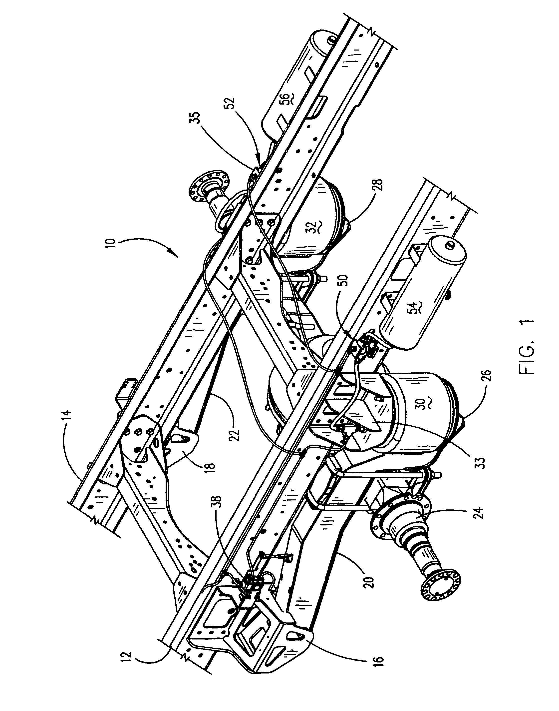
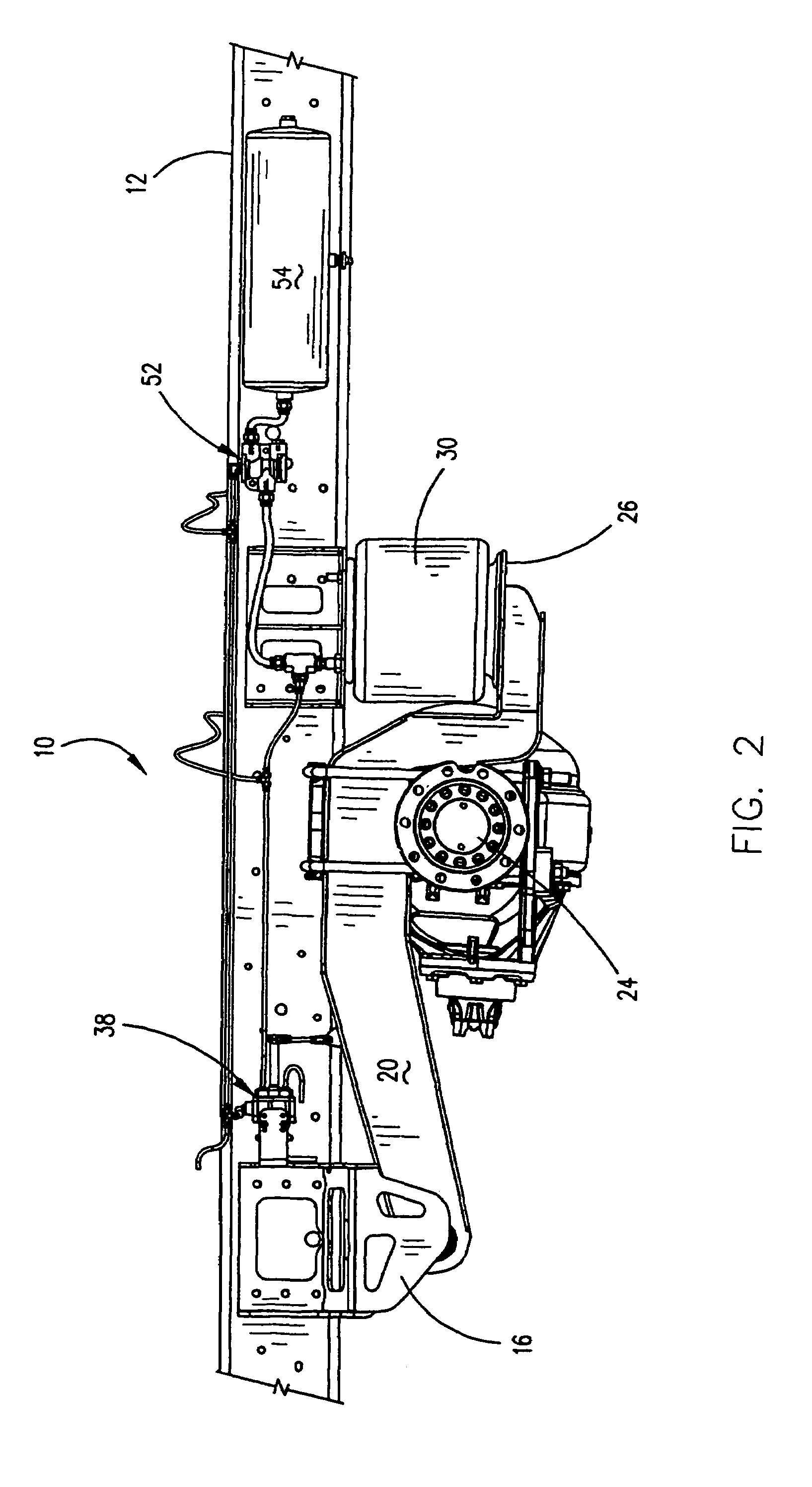
[0021]The numeral 10 refers generally to a vehicle such as a truck, ambulance, shuttle bus, bus, etc., with the vehicle 10 including a pair of longitudinally extending frame members 12 and 14, as illustrated in FIG. 1. Although the drawings herein illustrate the suspension system as being utilized on the rear of the vehicle, the suspension system could also be used at the forward end of the vehicle, if so desired. For purposes of illustration, FIG. 1 depicts the embodiment of FIG. 4 although the air dump valve is not shown. Although a particular air suspension system is shown in FIGS. 1 and 2, the system of this invention may be used on all suspension designs, not just the Link ULTRARIDE® suspension system.

[0022]In all the embodiments of FIGS. 3, 4 and 5, 6, mounting brackets 16 and 18 are secured to the frame members 12 and 14, respectively, forward of the rearward end thereof. Beams 20 and 22 are pivotally connected at their forward ends to the brackets 16 and 18, respectively, in...


PUM


Abstract

An air suspension system for a load bearing vehicle which includes a pair of air springs fluidly connected to a pair of auxiliary air reservoirs and to a main air reservoir. The system includes control valves which permit the air in the air springs to be exhausted therefrom to lower the vehicle frame without exhausting the air from the auxiliary air reservoirs.

Description

BACKGROUND OF THE INVENTION[0001]1. Field of the Invention[0002]This invention relates to an air suspension system for a vehicle and more particularly to an air suspension system for a vehicle which is designed to permit one end of the vehicle to be lowered or kneeled. Even more particularly, the air suspension system of this invention permits the exhaust of air from the air springs of the suspension system, while preventing the exhaust of air from the auxiliary air reservoirs of the suspension system.[0003]2. Description of the Related Art[0004]Link Manufacturing, Ltd. (“Link”) of Sioux Center, Iowa, markets an air suspension system under the trademark ULTRARIDE®. In the ULTRARIDE® system of Link Manufacturing, a pair of air springs are utilized to support the rear axle of the vehicle frame. In Link's prior art suspension system, the air may be exhausted from the air springs so that the rearward end of the vehicle frame may be lowered for loading purposes such as is desirable with ...

Claims


Application Information

Patent Timeline
Patent Type & Authority Patents(United States)
IPC IPC(8): B60G17/04B60G17/052
CPCB60G11/27B60G17/0523B60G2500/203B60G2500/2021B60G2202/154
Inventor SANDBULTE, ARLIN GENEJUNGJOHAN, CRAIG ALANVANDER KOOI, DAVID SHANE
Owner LINK MFG
Why Eureka
Try Eureka