Wireless communication system which improves reliability and throughput of communication and retransmission timeout determining method used for the same
- Summary
- Abstract
- Description
- Claims
- Application Information
AI Technical Summary
Benefits of technology
Problems solved by technology
Method used
Image
Examples
first embodiment
The First Embodiment
[0090]The embodiments of the present invention will be described below with reference to the drawings.
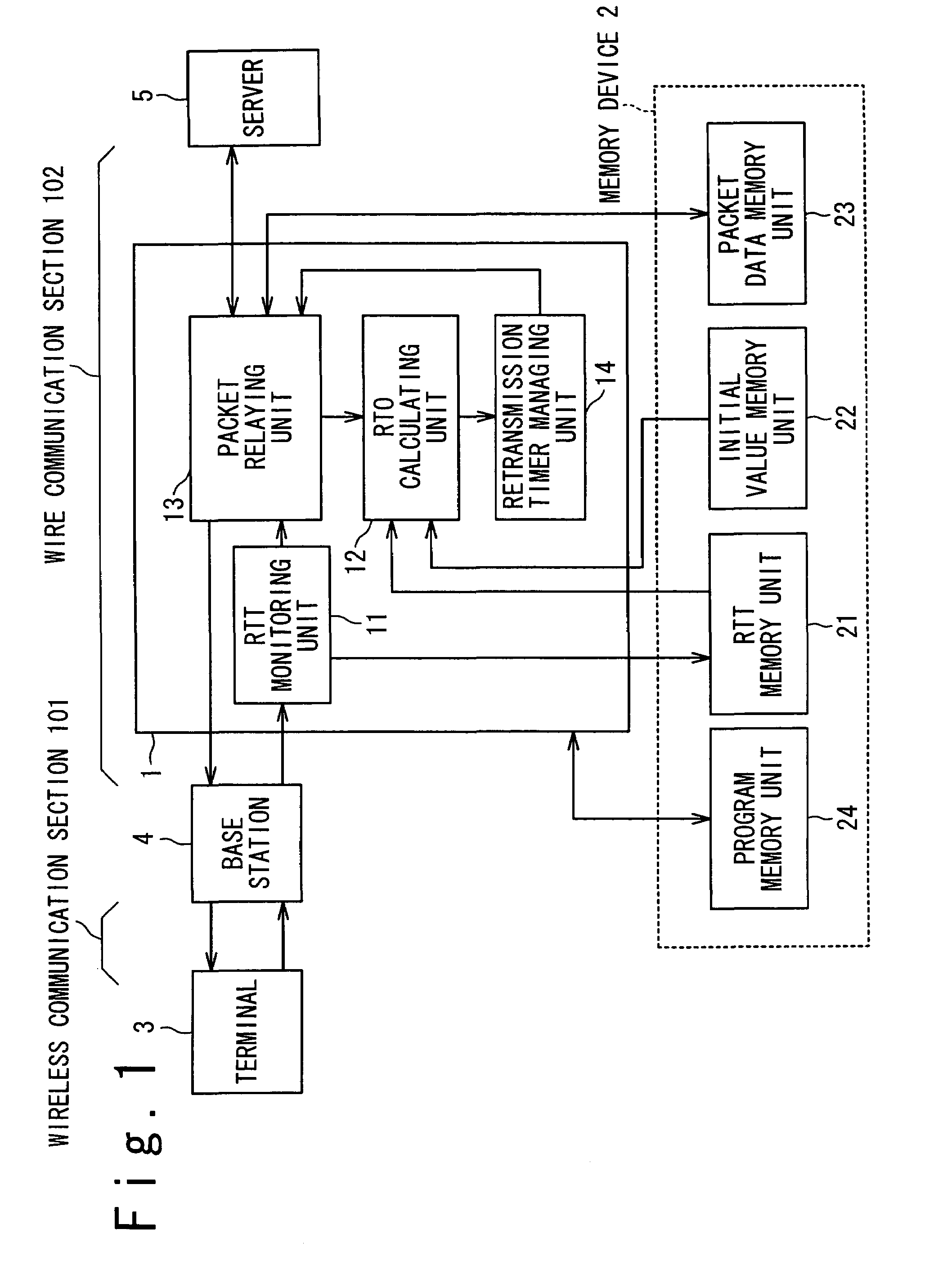
[0091]FIG. 1 is a block diagram showing a configuration of a wireless communication system according to a first embodiment in the present invention. In FIG. 1, the wireless communication system according to the first embodiment in the present invention includes a data relay apparatus (hereafter, referred to as a relay apparatus) 1, a terminal 3, a base station 4 and a server 5, and a memory device 2 is connected to the relay apparatus 1. The memory device 2 may be installed in the data relay apparatus 1. The relay apparatus 1, the terminal 3, the base station and the server 5 are the information processing apparatuses (processors).
[0092]The terminal 3 and the server 5 carry out the two-way communication, in which TCP / IP (Transmission Control Protocol / Internet Protocol) is used as a communication protocol, through the relay apparatus 1 and the base station 4. A se...
second embodiment
The Second Embodiment
[0135]FIG. 10 is a view showing a configuration example of an RTT memory unit according to a second embodiment in the present invention. In FIG. 10, the RTT memory unit 21 stores the set of expectation communication rates BRATE(BRATE#1, BRATE#2, BRATE#3, BRATE#4 , . . . , BRATE#m) and maximum change delay times (RTTchg) (RTTchg#1, RTTchg#2, RTTchg#3, RTTchg#4 . . . , RTTchg#m), which are correlated to traffic situations (T1, T2, T3, T4, . . . , Tm) and used under the traffic situations. Here, m and M (m=M) are positive integers.
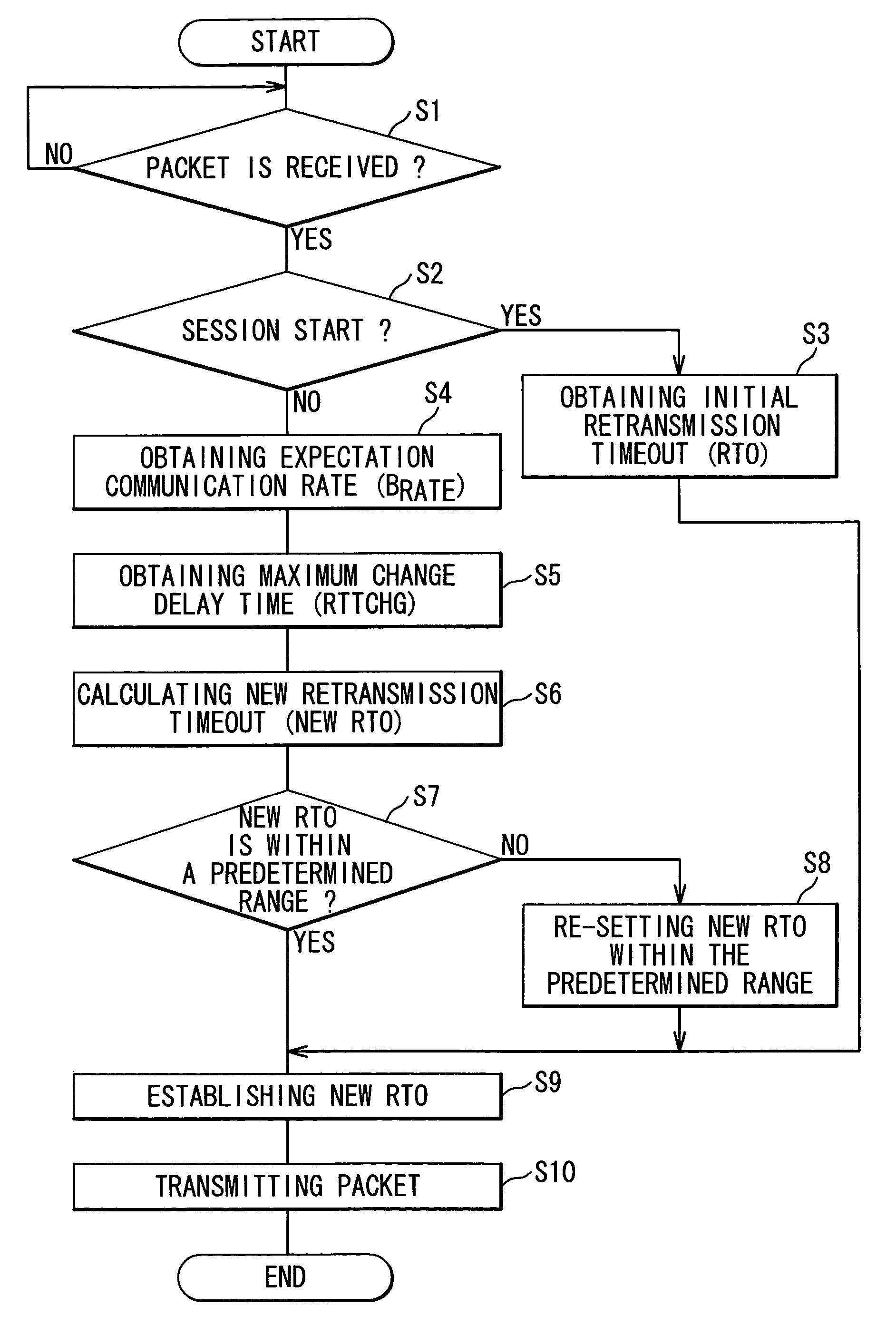
[0136]FIG. 11 is a flowchart showing the calculating process for the retransmission timeout (RTO) of the relay apparatus according to the second embodiment in the present invention. The configurations of the wireless communication system and the relay apparatus according to the second embodiment in the present invention are similar to those according to the first embodiment in the present invention shown in FIG. 1. The calculating process...
third embodiment
The Third Embodiment
[0143]FIG. 12 is a view showing a configuration example of an RTT memory unit according to a third embodiment in the present invention. In FIG. 12, the RTT memory unit 21 stores the set of expectation communication rates (BRATE) (BRATE#1, BRATE#2, BRATE#3, BRATE#4, . . . , BRATE#k) and maximum change delay times (RTTchg) (RTTchg#1, RTTchg#2, RTTchg#3, RTTchg#4. . . . , RTTchg#k), which are correlated to channel qualities (C1, C2, C3, C4, . . . , Ck) and used under the channel qualities. Here, k is a positive integer.
[0144]FIG. 13 is a flowchart showing the calculating process for the retransmission timeout (RTO) of the relay apparatus according to the third embodiment in the present invention. The configurations of the wireless communication system and the relay apparatus according to the third embodiment in the present invention are similar to those according to the first embodiment in the present invention shown in FIG. 1. The calculating process for the retran...
PUM
 Abstract
Description
Claims
Application Information
 - R&D
- Intellectual Property
- Life Sciences
- Materials
- Tech Scout
- Unparalleled Data Quality
- Higher Quality Content
- 60% Fewer Hallucinations
Browse by: Latest US Patents, China's latest patents, Technical Efficacy Thesaurus, Application Domain, Technology Topic, Popular Technical Reports.
© 2025 PatSnap. All rights reserved.Legal|Privacy policy|Modern Slavery Act Transparency Statement|Sitemap|About US| Contact US: help@patsnap.com


