Nestable and liftable oven rack

a technology of oven rack and lift, which is applied in the field of racks, can solve the problems of significant cost and energy saving, and achieve the effect of significant cost and energy saving, and volume reduction

Inactive Publication Date: 2008-09-02
M & E MFG
View PDF49 Cites 26 Cited by
  • Summary
  • Abstract
  • Description
  • Claims
  • Application Information

AI Technical Summary

Benefits of technology

[0015]A still further object of the invention is to provide a rack which can be factory assembled, and shipped cost-effectively assembled, owing to the reduced volume required by each nested rack. Such leads to significant cost and energy savings.

Problems solved by technology

Such leads to significant cost and energy savings.

Method used


Image

  • Nestable and liftable oven rack
  • Nestable and liftable oven rack
  • Nestable and liftable oven rack

Examples


Embodiment Construction

FIGS. 1-2

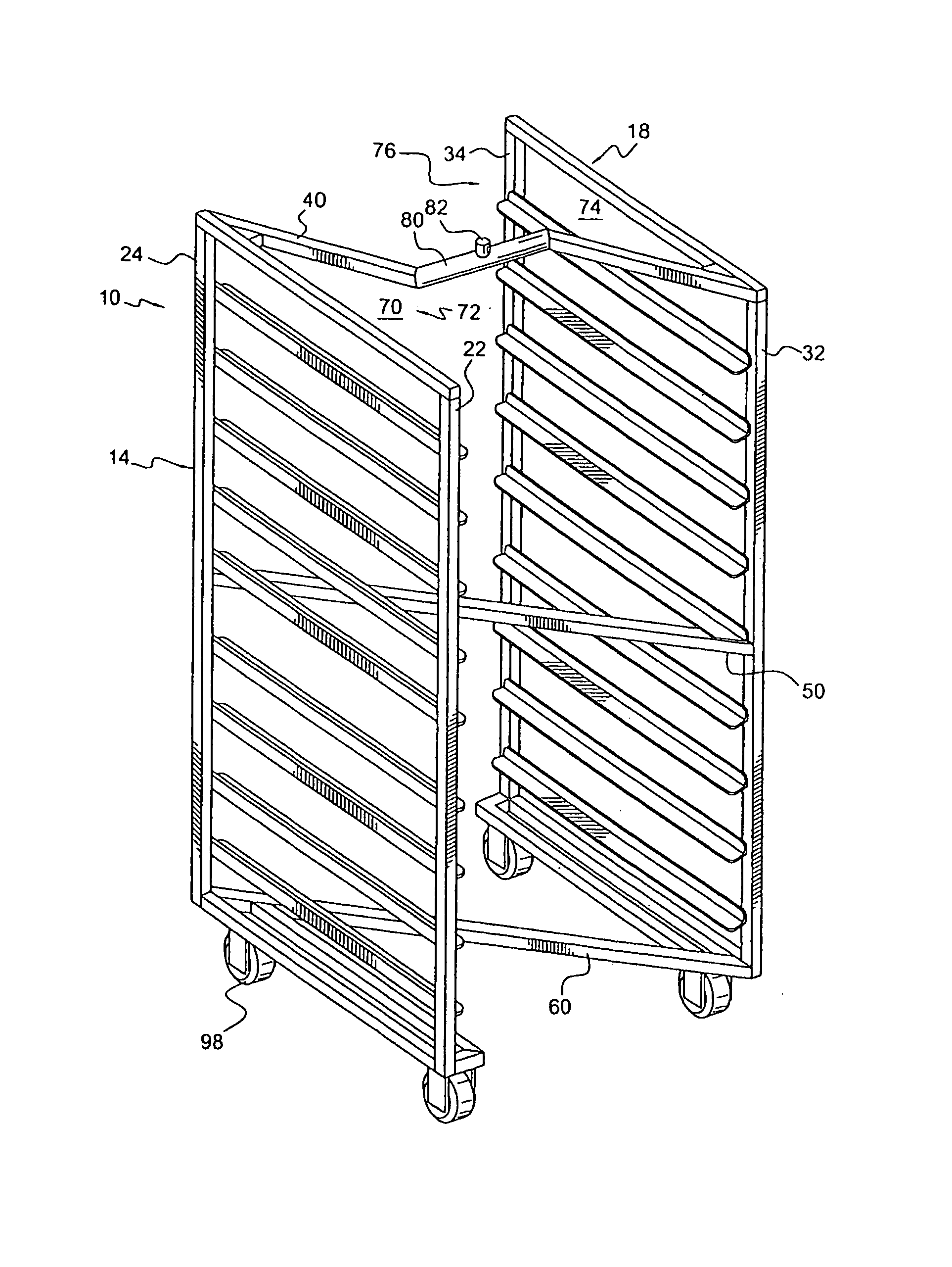
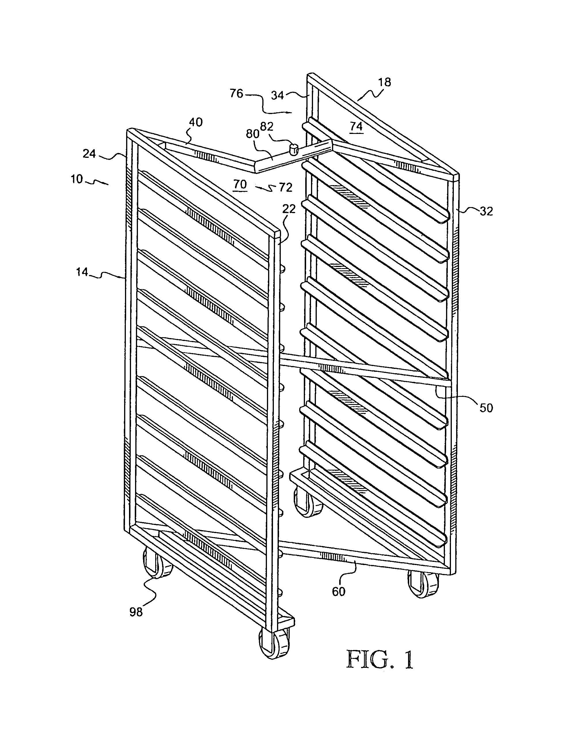
[0058]FIGS. 1-2 illustrate a first preferred embodiment of the invention.

[0059]A rack 10 includes a left upright frame 14 and a spaced apart right upright frame 18.

[0060]Left frame 14 includes a left front post 22 and a left rear post 24, and said front and rear posts 22, 24 being connected by an upper member and a lower member, respectively, to form a generally rectangular frame. Likewise, right upright frame 18 includes a right front post 32 and a right rear post 34, and said front and rear posts 32, 34 being connected by an upper member and a lower member, respectively, to form a generally rectangular frame. The upper members of the respective left and right frames may likewise be termed top left and top right frame connectors, as set forth below regarding FIG. 8, for example.

[0061]An upper connector 40 connects left frame 14 to right frame 18. Typically, upper connector 40 may be made of square tubing, and bolted, or welded, to left and right frames 14, 18, respectively...


PUM


Abstract

Rack includes a left upright frame, a right upright frame, and a connector extending between and joining the left and right frames. The connector defines at least one passage extending along the left upright frame, for example, so that another rack may be nested within a volume defined by the rack for reducing storage space requirements. The rack may have its connector oriented so that the rack has a substantially Z-shaped frame, a substantially X-shaped frame, a substantially U-shaped frame, a substantially V-shaped frame, or a substantially H-shaped frame, for example, when viewed from above. A lifting element may be provided on an upper portion of the rack for use with institutional and industrial lifting mechanisms. The lifting element may be mounted on the rack so as to avoid interference with another rack when the racks are nesting.

Description

CROSS-REFERENCE TO RELATED APPLICATIONS[0001]This application is a continuation-in-part of application Ser. No. 10 / 195,411, filed Jul. 16, 2002 now U.S. Pat. No. 6,974,042, which application Ser. No. 10 / 195,411 is a continuation-in-part of application Ser. No. 08 / 847,483, filed Apr. 25, 1997, now U.S. Pat. No. 6,419,098, issued Jul. 16, 2002, and which claims the priority of provisional application No. 60 / 034,853, filed Jan. 28, 1997, entitled “Nestable and / or Liftable Rack”, and which claims the priority of provisional application No. 60 / 017,343, entitled “Nesting Oven Racks Equipped with Brackets for Lifting the Rack”, filed Apr. 26, 1996, and each of which is incorporated herein by reference.[0002]This application is a continuation-in-part of Applicant's co-pending application Ser. No. 10 / 183,565, filed Jun. 28, 2002 now abandoned, entitled “V-Shaped Nestable Tray Rack”, which is incorporatedFIELD OF THE INVENTION[0003]This invention relates to a rack.[0004]More particularly, thi...

Claims


Application Information

Patent Timeline
Patent Type & Authority Patents(United States)
IPC IPC(8): A47F3/14
CPCA21B1/44A21B3/00B62B3/188B62B3/002A47F5/137
Inventor HALL, DONALD M.
Owner M & E MFG
Why Eureka
Try Eureka