
Actuator unit for a piezo-controlled fuel injection valve

a piezoelectric actuator and fuel injection valve technology, applied in fuel injecting pumps, generators/motors, machines/engines, etc., can solve the problems of valve-closure members lifting away, actuators contracting, valve expansion, etc., to prolong the service life of actuator units, reduce spring rigidity of the hollow body, and strengthen the hollow body

Inactive Publication Date: 2008-09-02
ROBERT BOSCH GMBH
View PDF14 Cites 8 Cited by
  • Summary
  • Abstract
  • Description
  • Claims
  • Application Information

AI Technical Summary

Benefits of technology

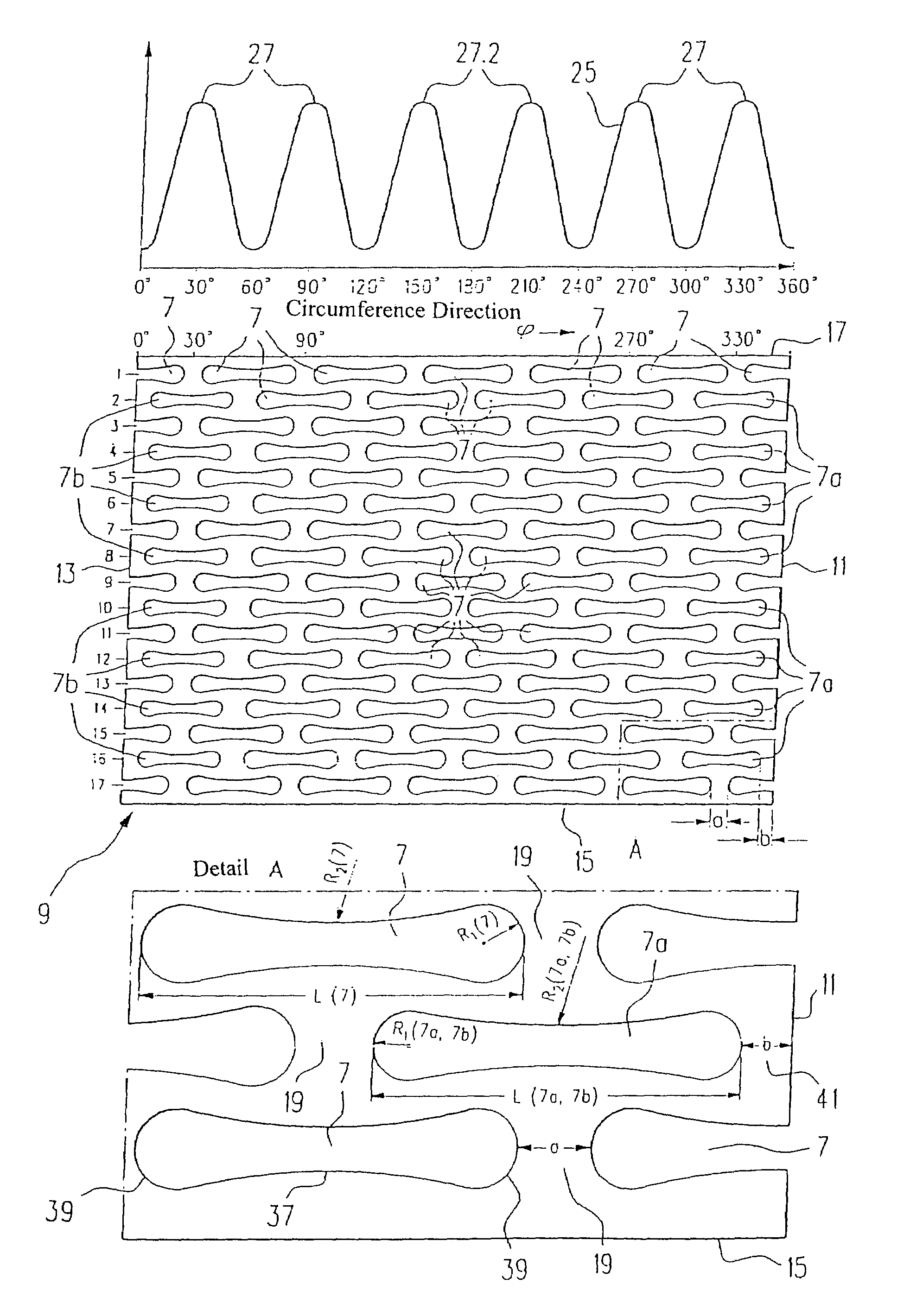
The present invention relates to an actuator unit with a hollow body and a piezoelectric actuator. The hollow body has a joint that connects two parts of the body. The invention provides a solution to the problem of uneven force distribution on the piezoelectric actuator caused by the joint. By designing the recesses in the blank with a smaller radius adjacent to the joint and a wider radius in the region between the joint and the rest of the recesses, the hollow body compensates for the reduced spring rate in the joint region. This results in a spring rate that is constant and symmetrical over the entire circumference of the hollow body. The invention also provides a solution to the problem of lateral forces transmitted to the actuator by using wider bridge pieces in the region of the joint. The recesses are bone-shaped and extend lateral to the longitudinal axis of the hollow body. The invention improves the behavior of the hollow body and increases the service life of the actuator unit.

Problems solved by technology

A fuel injection valve with a piezoelectric actuator is triggered by applying an electric voltage to the piezoelectric actuator; this causes a rapid expansion of the piezoelectric actuator due to known physical effects of piezoelectric ceramic and causes a valve-closure member to lift away from a valve seat.
If the voltage applied to the actuator is reduced, this causes the actuator to contract.
As a function of the triggering speed, the inertia of the previously accelerated mass of the actuator generates damaging tensile forces in the piezoelectric actuator, in particular causing fractures in the soldered connections between the individual layers of the piezoelectric actuator.
Among other things, the welding of the first joint has the following disadvantages: the welding causes a generally undesirable structural change to the hollow body in the immediate vicinity of the welding seam.
A second problem is the spatters produced during the welding, which can lead to difficulties in assembly of the actuator unit or can even lead to functional failures of the fuel injection valve when one or more spatters come loose during operation.
A third problem is a sinking-in of the welding seam (seam sinkage) at the beginning and end of the welding seam and the resulting notch effect and voltage spikes.

Method used


Image

  • Actuator unit for a piezo-controlled fuel injection valve
  • Actuator unit for a piezo-controlled fuel injection valve
  • Actuator unit for a piezo-controlled fuel injection valve

Examples


Embodiment Construction

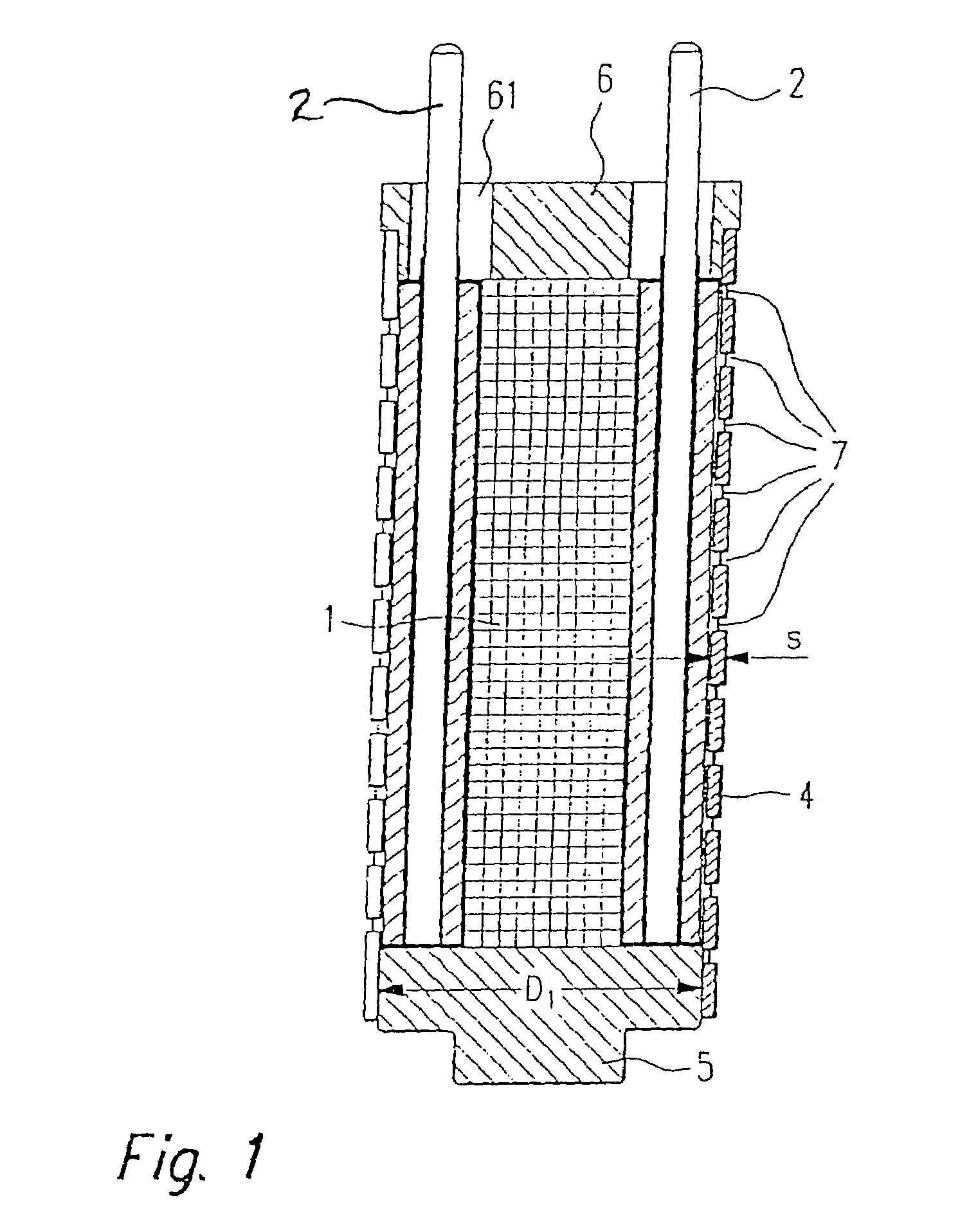
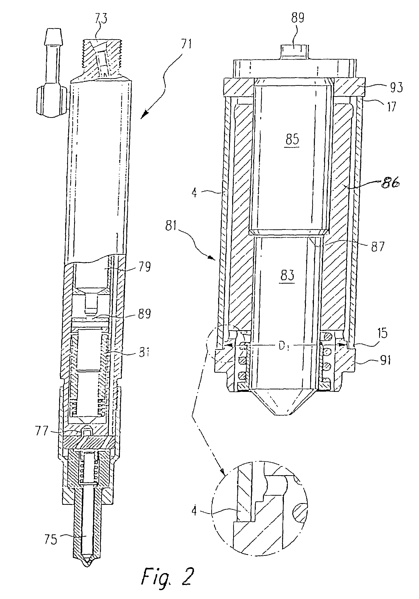
[0055]FIG. 1 shows a first exemplary embodiment of an actuator unit according to the present invention. The actuator unit is comprised of a piezoelectric actuator 1, which can be comprised of a number of stacked individual piezoelectric elements (not shown). The piezoelectric actuator 1 is triggered via contacting pins 2 that are disposed alongside the actuator 1 and are connected to the actuator 1 in an electrically conductive fashion. The application of a voltage between the contact pins 2 produces a longitudinal expansion of the piezoelectric actuator 1, which is used, for example, to control an injection valve in an internal combustion engine. The piezoelectric actuator 1 with the contact pins 2 is disposed inside a hollow body 4 embodied in the shape of a tubular spring. The ends of the piezoelectric actuator 1 each rest against a respective cover plate 5, 6, the upper cover plate 6 being provided with feedthroughs 61 through which the contact pins 2 extend. The upper and lower...


PUM


Abstract

An actuator unit suitable for actuating a fuel injection valve of an injection system for internal combustion engines is comprised of a piezoelectric actuator and a hollow body embodied in the form of a spring. Embodying the hollow body according to the present invention can extend the service life of the actuator unit.

Description

CROSS-REFERENCE TO RELATED APPLICATIONS[0001]This application is a 35 USC 371 application of PCT / DE 2004 / 000565 filed on Mar. 19, 2004.BACKGROUND OF THE INVENTION[0002]1. Field of the Invention[0003]The invention relates to an improved actuator unit comprised of a piezoelectric actuator.[0004]2. Description of the Prior Art[0005]Actuator units of the type with which this invention is concerned are use among other things in fuel injection systems and in particular in fuel injection valves since the switching times of such actuator units are very short. The short switching times permit a more exact metering of the injected fuel quantity and permit an improved shape of the injection curve over time. In connection with the present invention, the generic term “fuel injection valve” is understood to mean all types of fuel injection values, for example, the injectors for common rail injection systems or injection nozzles of conventional fuel injection systems. A fuel injection valve with a...

Claims


Application Information

Patent Timeline
Patent Type & Authority Patents(United States)
IPC IPC(8): H01L41/08F16F1/02H02N2/04H10N30/00H10N30/50F02M47/02F02M51/06F02M59/46F02M61/16F02M63/00F02M63/02H10N30/88
CPCF02M47/027F02M61/167F02M61/168H01L41/053F02M63/0225F16F1/028F02M63/0026F02M2200/26H10N30/886F02M59/46F16F1/02F02M47/02F02M61/16
Inventor KIENZLER, DIETERUHLMANN, DIETMAR
Owner ROBERT BOSCH GMBH
Learn More