Fast clock acquisition enable method using phase stir injection to PLL for burst mode optical receivers

a technology of optical receivers and enable methods, applied in pulse techniques, reradiation, instruments, etc., can solve the problems of no existing devices using discrete phase correlation pll architectures, data in packets may actually be lost, and cannot distinguish between a 0 degree phase shift and a 180 degree phase shift, so as to prolong the synchronization time, the time required to synchronize the internal clock with the received data is always shortened.

Inactive Publication Date: 2008-09-02
S AQUA SEMICONDUCTOR LLC
View PDF21 Cites 4 Cited by
  • Summary
  • Abstract
  • Description
  • Claims
  • Application Information

AI Technical Summary

Benefits of technology

[0014]The various embodiments of the invention may provide a number of advantages over the prior art. For example, a system in accordance with one embodiment of the invention achieves phase alignment in less than 30 ns in the worst case. Comparable PLLs which do not have perturbation signals injected into them may have worst case performance of 200 ns. Another significant advantage that may be provided is that the time required to synchronize the internal clock with the received data is always shortened (as compared with an equivalent PLL without the injection of the perturbation signal), while other signal injection approaches may actually push the system into the “trap” at 180 degrees, thereby lengthening the synchronization time. Additional advantages may also be provided.

Problems solved by technology

Moreover, if it takes too long to synchronize the receiver with the packet, the data in the packet may actually be lost.
One problem with these approaches is that there are no existing devices using discrete phase correlation PLL architectures that operate at rates higher than 10 Gbps (gigabits per second).
Another problem with these architectures is that they typically cannot distinguish between a 0 degree phase shift and a 180 degree phase shift.
As a result, they may cause the system to stabilize out of phase or, in a more optimistic case, take a very long time to stabilize in phase.
The problem with this system is, as noted above, that signals which are 180 degrees out of phase may look the same to the system as signals which are in phase.
While this may not always cause these systems to remain out of phase, it will typically cause the systems to take a substantially greater amount of time to align the phases of the signals.

Method used


Image

  • Fast clock acquisition enable method using phase stir injection to PLL for burst mode optical receivers
  • Fast clock acquisition enable method using phase stir injection to PLL for burst mode optical receivers
  • Fast clock acquisition enable method using phase stir injection to PLL for burst mode optical receivers

Examples


Embodiment Construction

[0025]A preferred embodiment of the invention is described below. It should be noted that this and any other embodiments described below are exemplary and are intended to be illustrative of the invention rather than limiting.

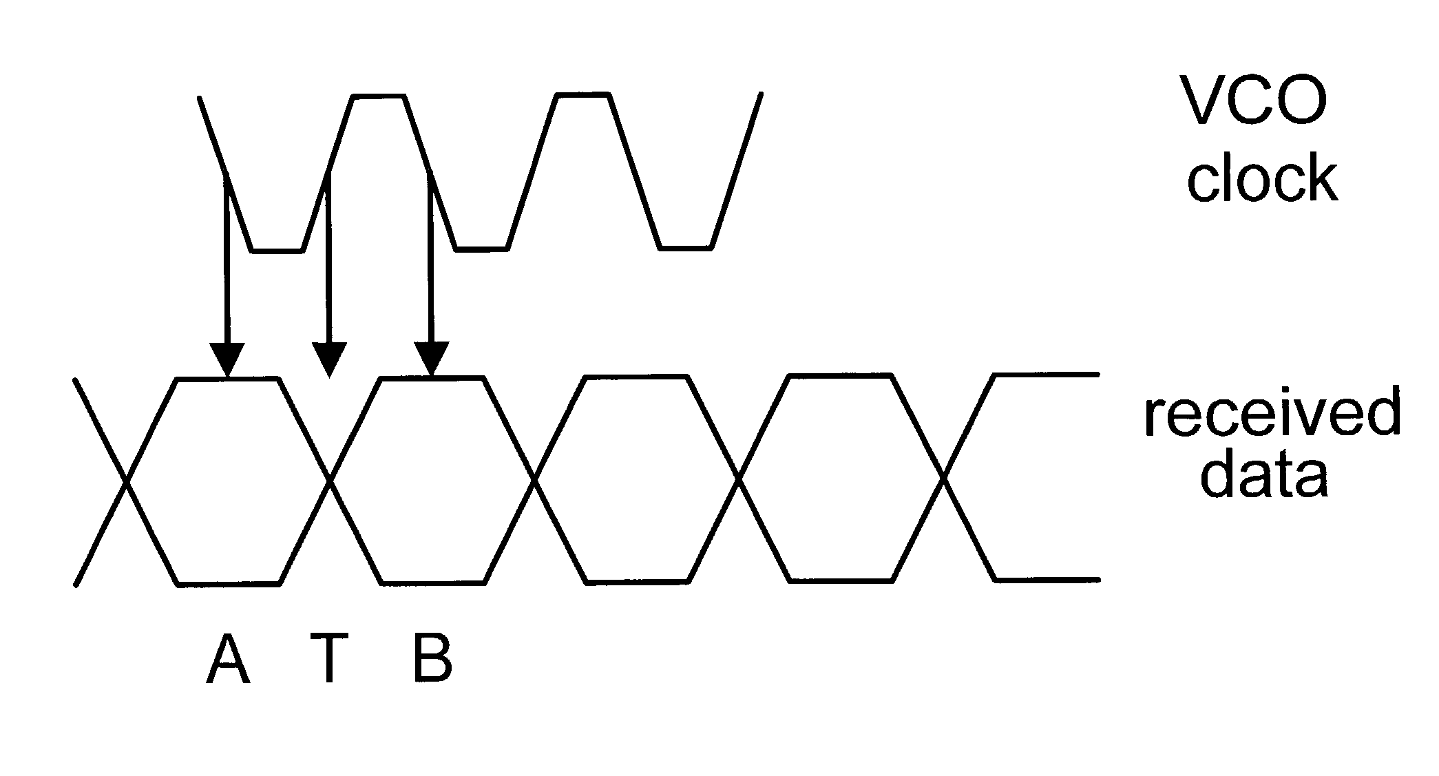
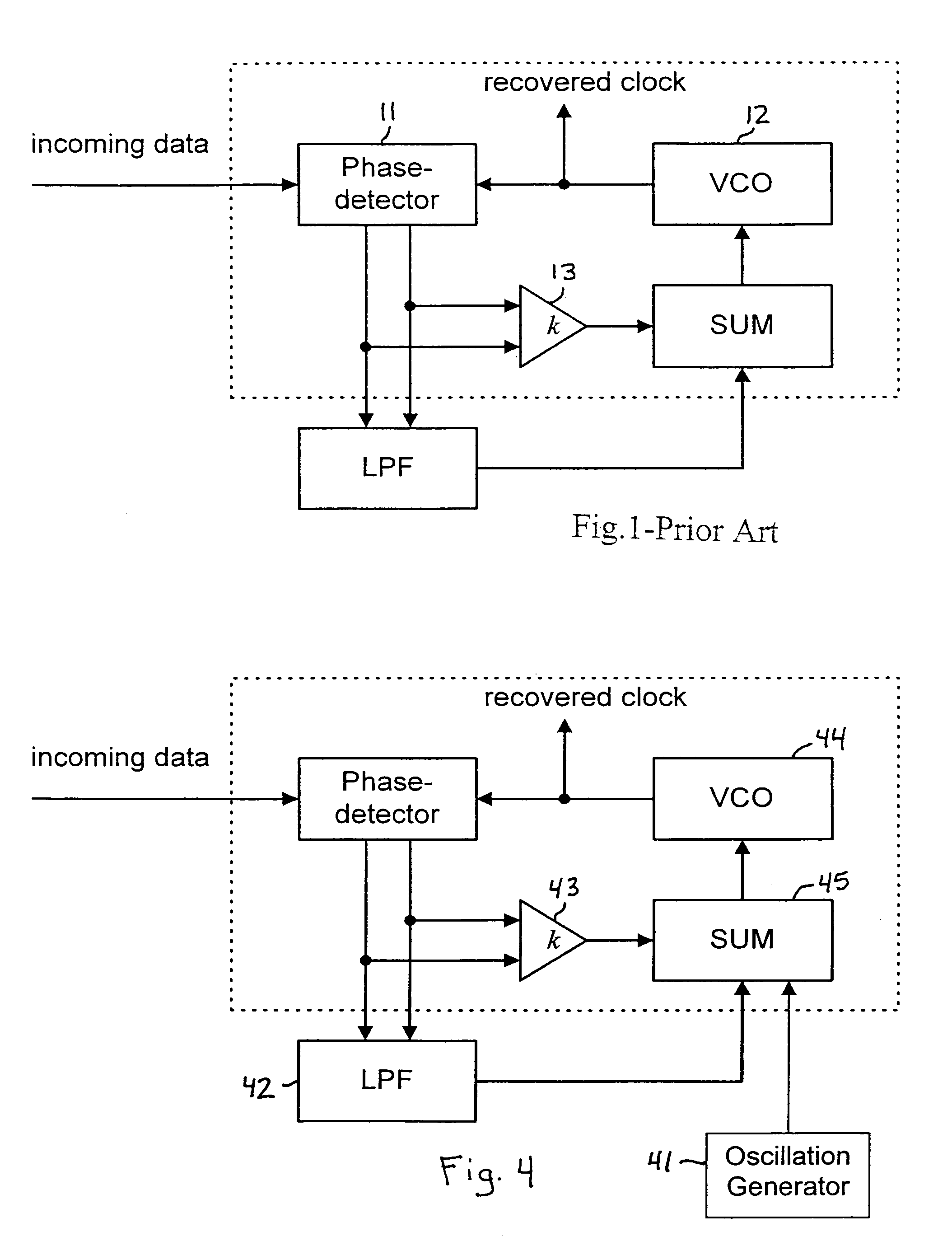
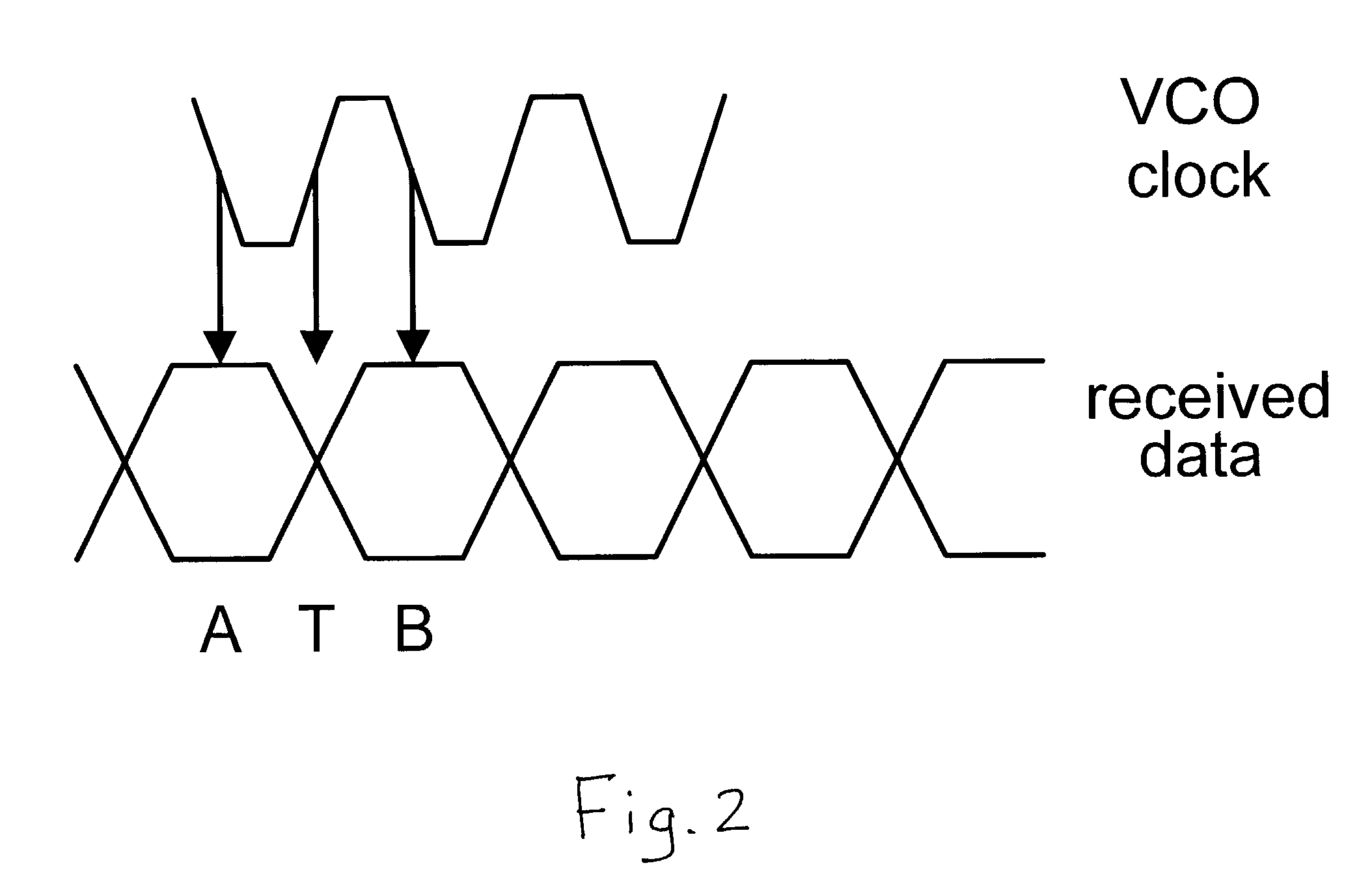
[0026]Broadly speaking, the invention comprises improved systems and methods for fast acquisition of a clock signal. In one embodiment, the present system is based upon a double-loop PLL architecture. Since this type of architecture normally has poor acquisition speed when the clock signal to be recovered is around 180 degrees out of phase with the VCO signal, an oscillating signal is injected into the VCO signal. The purpose of injecting this signal is to bump the system out of the quasi-stable state around 180 degrees and to allow the system to stabilize in phase (0 or 360 degrees out of phase). The oscillating signal is damped so that it will not hinder stabilization of the system with the signals in phase.

[0027]It should be noted that, for the purposes of th...


PUM


Abstract

Systems and methods for aligning the phase of a PLL with an incoming data signal. In one embodiment, when a data signal is received in a PLL, a phase perturbation signal is generated and injected into the PLL. The PLL then performs a phase alignment procedure to lock on to the received data signal. The phase perturbation signal is a damped sinusoidal oscillation that is injected into the PLL when each of a plurality of data packets is received. The perturbation signal has an amplitude sufficient to bump the PLL out of a quasi-stable state around 180 degrees out of phase with the incoming data signal, but is damped to less than a degree of phase shift within 30 ns of being injected.

Description

RELATED APPLICATIONS[0001]This application claims priority to U.S. Provisional Patent Application No. 60 / 375,663, entitled “Apparatus and Method for High Bit Rate Burst Mode Receiver”, filed Apr. 26, 2002 by Bing Li, et al., which is incorporated by reference as if set forth herein in its entirety.FIELD OF THE INVENTION[0002]The invention relates generally to data communications and more particularly to systems and methods for increasing the speed with which a receiver can synchronize its internal clock with a clock signal embodied in a received data packet.BACKGROUND OF THE INVENTION[0003]In a TDM (time division multiplexed) data transmission system, it is not particularly important that the system be able to quickly recover a clock signal embodied in received data. In these systems, data is continuously received at what is essentially a constant level and with a constant phase. Consequently, once the appropriate level and phase are identified, they are not likely to change very of...

Claims


Application Information

Patent Timeline
Patent Type & Authority Patents(United States)
IPC IPC(8): H03D3/24
CPCH03L7/093H03L7/24H03L7/10H04L7/033
Inventor LI, BINGWOLF, DAVIDPLESA, JAMESTAMIL, LAKSHMAN S.
Owner S AQUA SEMICONDUCTOR LLC
Why Eureka
Try Eureka