Eureka AIR delivers breakthrough ideas for toughest innovation challenges, trusted by R&D personnel around the world.

Method and system for controlling power in a chip through a power-performance monitor and control unit

a technology of power-performance monitor and control unit, which is applied in the direction of liquid/fluent solid measurement, instruments, sustainable buildings, etc., can solve the problems of not meeting the power budget and clock-gate alone is not enough to meet the chip-level power, and achieve the effect of increasing performan

Active Publication Date: 2008-09-02
IBM CORP
View PDF10 Cites 71 Cited by
  • Summary
  • Abstract
  • Description
  • Claims
  • Application Information

AI Technical Summary

Benefits of technology

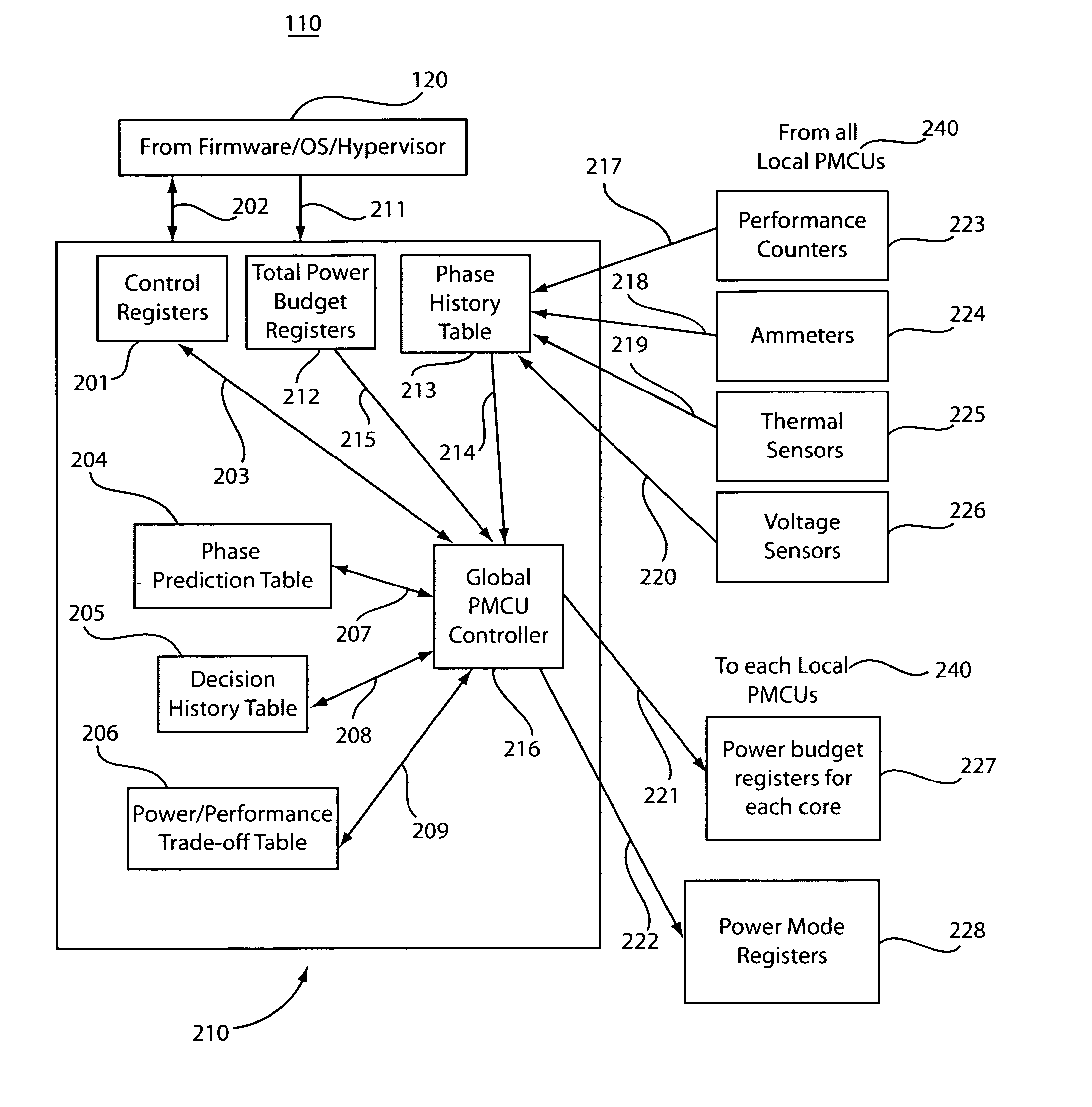
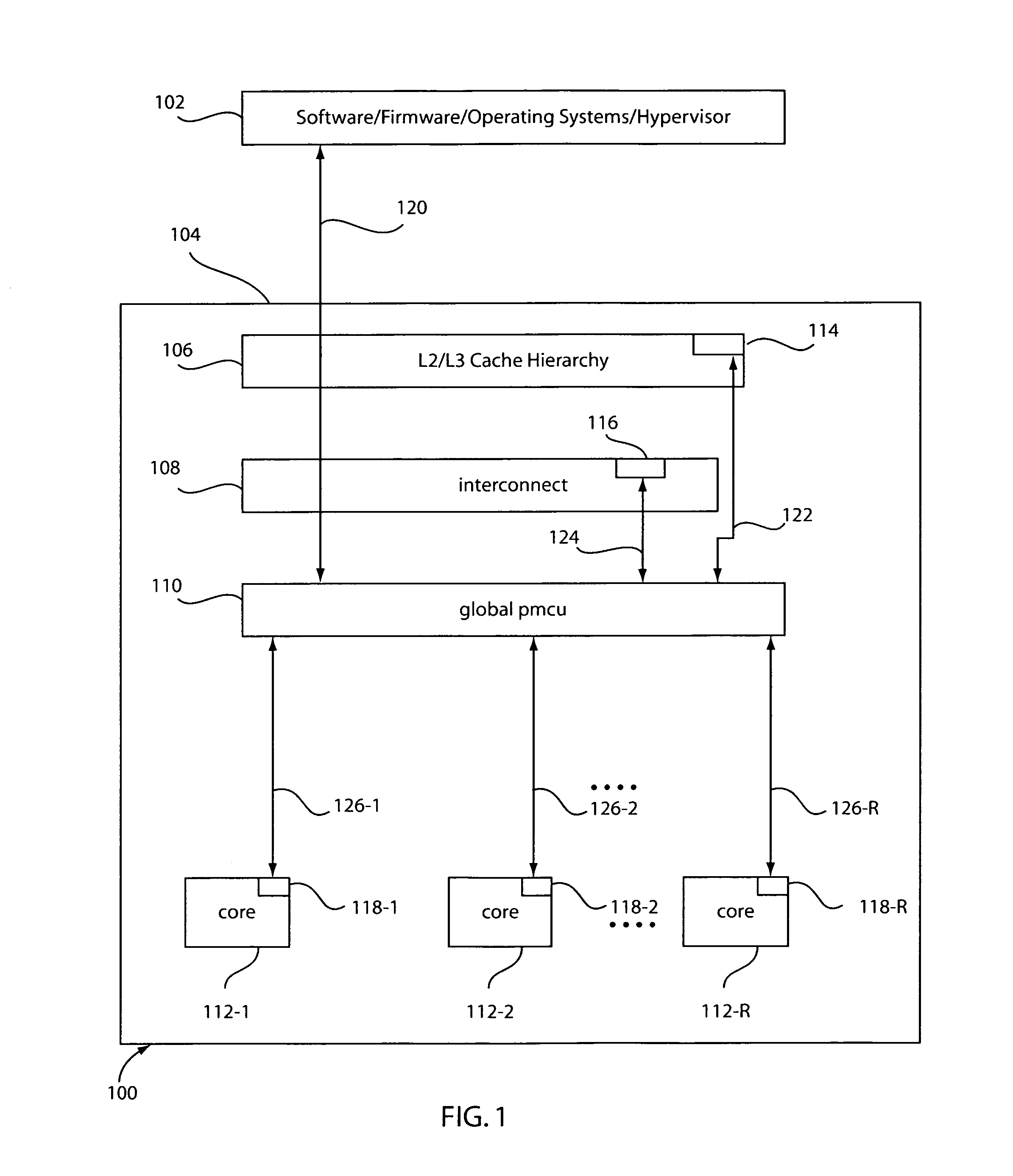
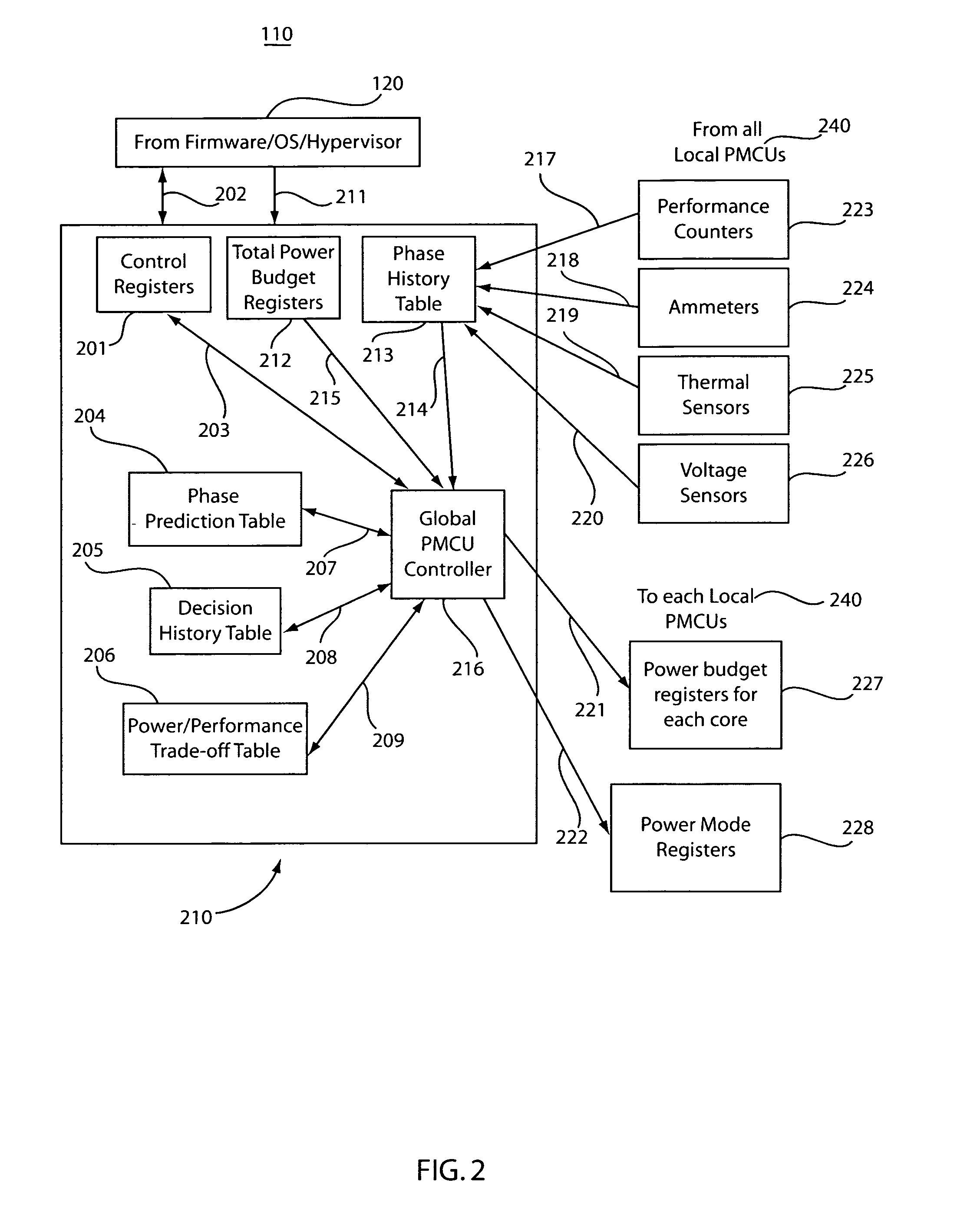
[0013]The maximum power limit for the chip (or system) may be provided by the topmost layer of the control hierarchy (e.g. the one with the highest authority), and may be changed occasionally, in response to global conditions external to the domain of control of the full hierarchical control system stipulated. The peak temperature limit of the chip (or system) may be a preset design specification, determined by the package / cooling solution engineered for the chip (or system). The performance may be targeted for maximization by one or more of the following: (a) use and deployment of one or more additional cores (that would otherwise be powered off or excluded from the design in the absence of a dynamic power management method such as described herein); and (b) at a given response point, and given a choice of power mode allocations per core, make an allocation such as to maximize the chip (or system)—level throughput performance.
[0019]A local PMCU control loop may be implemented in hardware as a closed loop finite state controller, wherein the target power budget for each physically monitored resource is achieved through application of the suggested power mode (received from the global PMCU). Any available power slack is capitalized upon by increasing performance, using the command set available for autonomous control at the local PMCU level.

Problems solved by technology

In a multi-core processor, the chip-level performance targets are aggressive, and meeting the power budget at high performance levels presents a major design challenge.
Several analysis have shown that clock-gating alone is not enough to meet the chip-level power budget for multi-core designs that could meet the chip-level performance requirements.

Method used


Image

  • Method and system for controlling power in a chip through a power-performance monitor and control unit
  • Method and system for controlling power in a chip through a power-performance monitor and control unit
  • Method and system for controlling power in a chip through a power-performance monitor and control unit

Examples


Embodiment Construction

[0029]Embodiments of a power-performance monitor and control unit (PMCU) preferably form an integral part of a microprocessor design. Systems and methods are described for controlling power consumption of a microprocessor chip or microprocessor-based system where the power of the chip (or system) is maintained within a programmable limit; the peak temperature across monitored regions of the chip (or system) is maintained to be below a specified limit; and the net throughput performance of the chip (or system) is targeted for maximization, within the specified constraints of power and temperature.

[0030]One objective of PMCU is to address the challenge of reducing power by exploiting the variability within a workload and between different workloads. Several different objectives can be pursued.

[0031]For example, given a chip which has X watts power limit due to packaging / cooling constraints, the chip can only fit Y amount of cores and Z amount of level 2 memory (e.g., L2 cache) without...


PUM


Abstract

A system and method for controlling power and performance in a microprocessor system includes a monitoring and control system integrated into a microprocessor system. The monitoring and control system includes a hierarchical architecture having a plurality of layers. Each layer in the hierarchical architecture is responsive to commands from a higher level, and the commands provide instructions on operations and power distribution, such that the higher levels provide modes of operation and budgets to lower levels and the lower levels provide feedback to the higher levels to control and manage power usage in the microprocessor system both globally and locally.

Description

GOVERNMENT RIGHTS[0001]This invention was made with Government support under Contract No.: NBCH30390004 awarded by the Defense Advanced Research Projects Agency (DARPA). The Government has certain rights in this invention.BACKGROUND[0002]1. Technical Field[0003]The present invention relates generally to dynamic management and control of power and performance for an integrated circuit chip, and more specifically, to systems and methods for a power / performance monitoring and control unit that can improve instruction throughput and power management.[0004]2. Description of the Related Art[0005]Chip-level power dissipation limits constitute a fundamental design constraint in future high-performance microprocessors. In a multi-core processor, the chip-level performance targets are aggressive, and meeting the power budget at high performance levels presents a major design challenge. On-chip, dynamic power management is therefore a design feature that needs to be considered as an integral p...

Claims


Application Information

Patent Timeline
Patent Type & Authority Patents(United States)
IPC IPC(8): G06F1/26G06F1/32
CPCG06F1/206G06F1/3203Y02B60/1275Y02D10/00
Inventor BOSE, PRADIPBUYUKTOSUNOGLU, ALPERCHER, CHEN-YONGKUDVA, PRABHAKAR N.
Owner IBM CORP
Why Eureka
Eureka Blog
Learn More