
Method of using a shape memory material as a mandrel for composite part manufacturing

Inactive Publication Date: 2008-09-09
SPINTECH LLC
View PDF32 Cites 94 Cited by
  • Summary
  • Abstract
  • Description
  • Claims
  • Application Information

AI Technical Summary

Benefits of technology

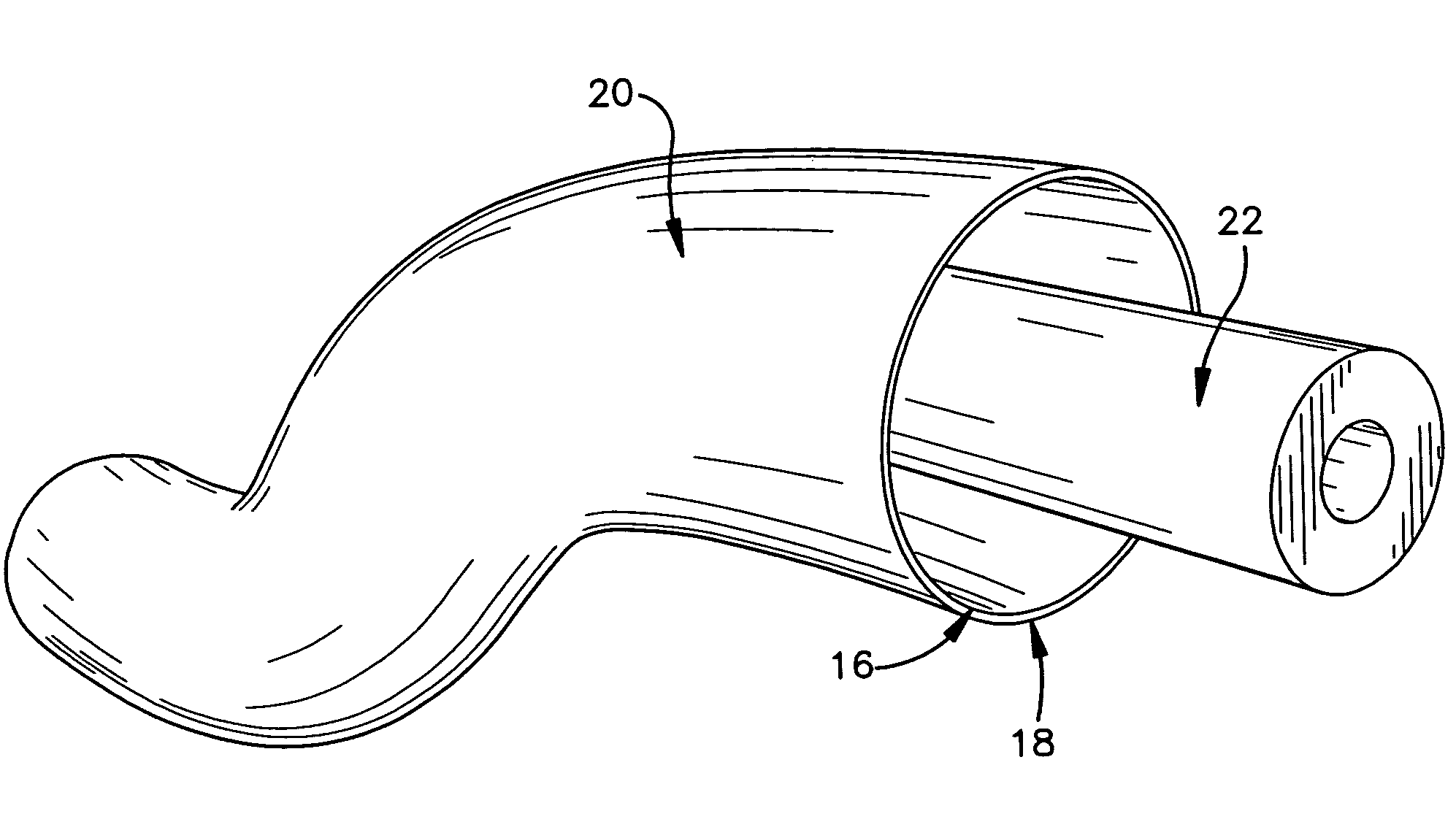
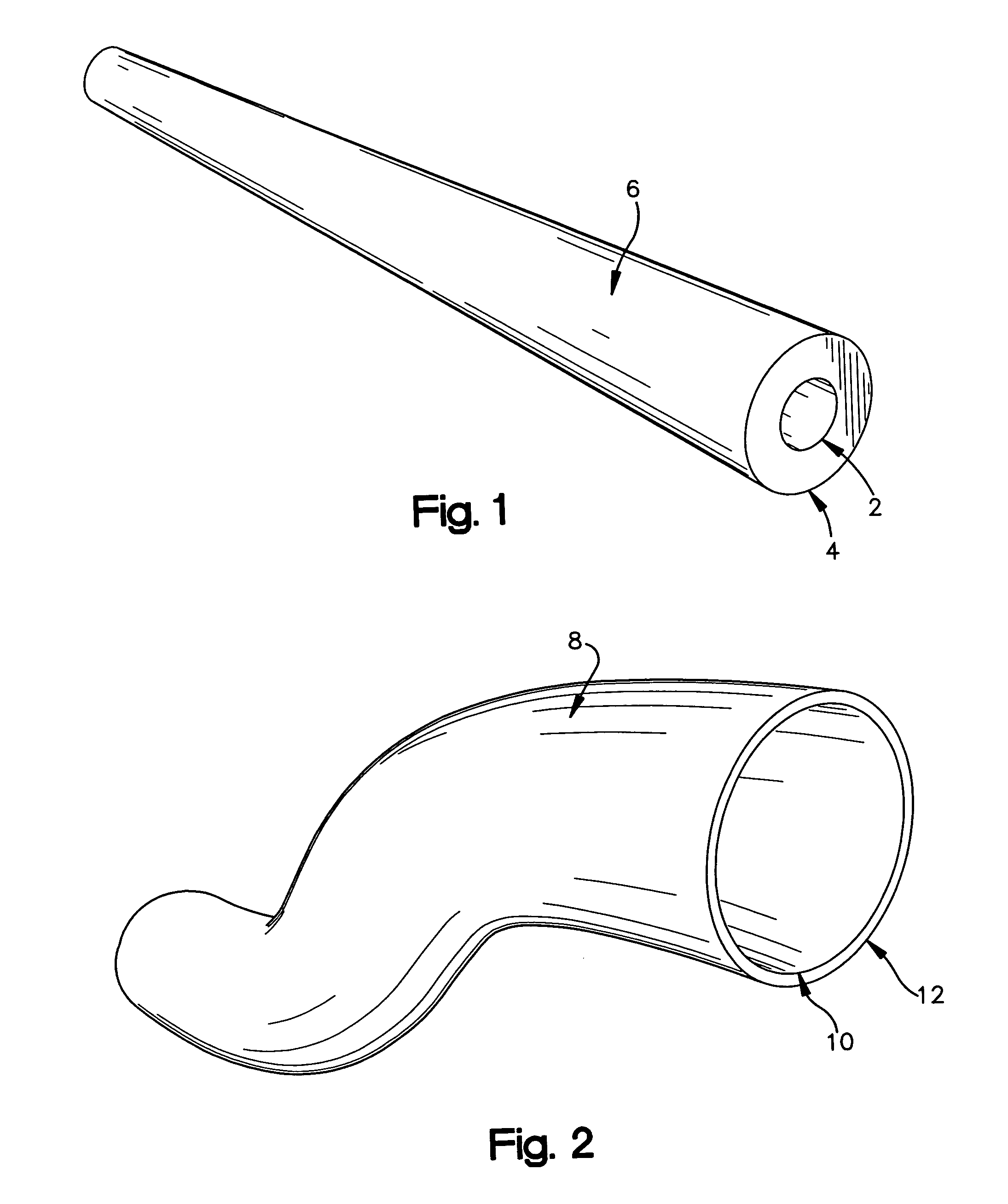
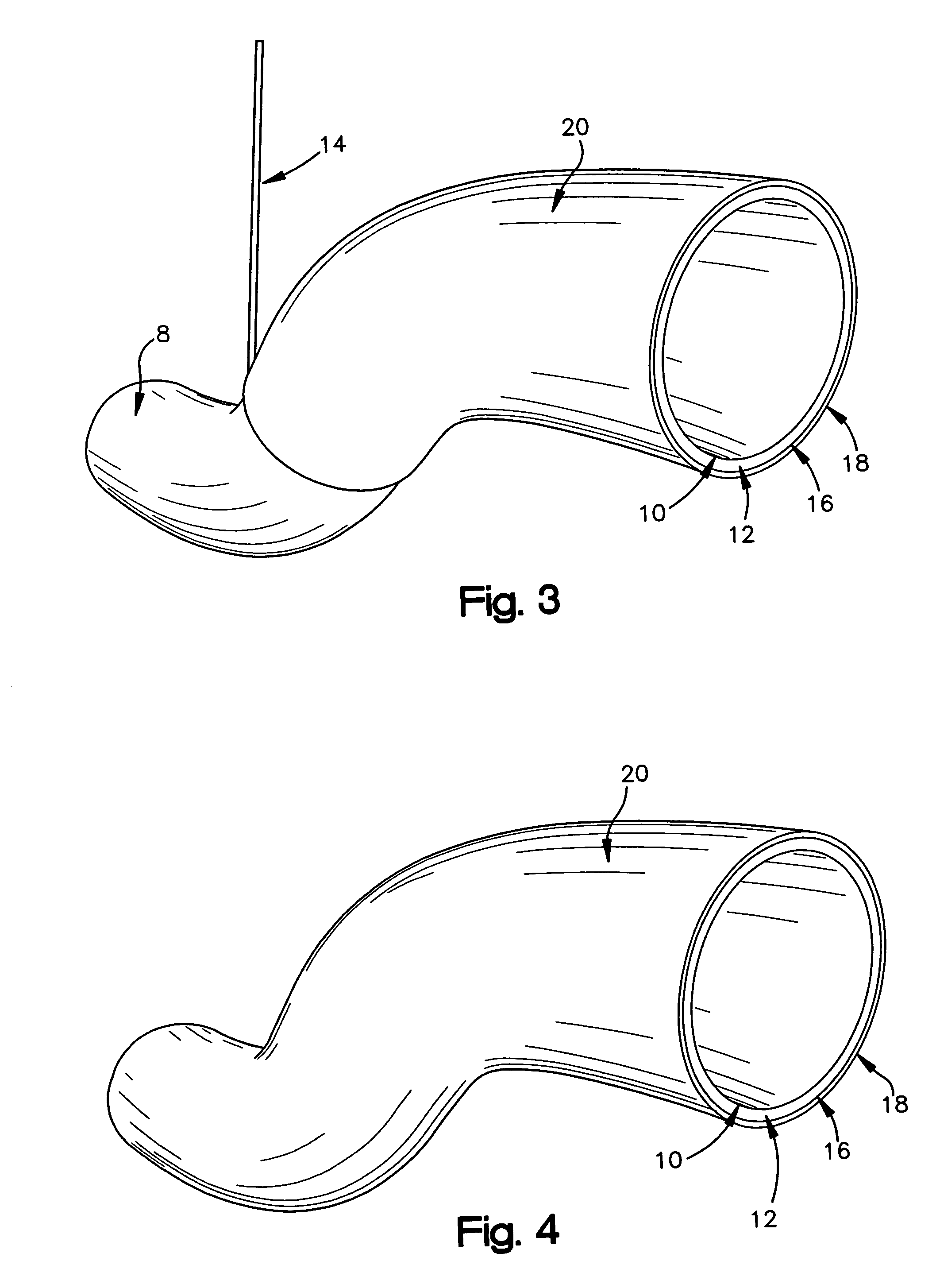
[0019]In one exemplary embodiment of the invention, the method includes the steps of providing a pre-formed tube of Shape Memory Polymer (SMP), using a mold to deform the SMP tube to replicate the mold forming a SMP mandrel, filament winding resin soaked fibers around the deformed SMP mandrel, curing the resin, causing the deformed SMP Mandrel to return to its original smaller shape, and quickly and easily removing the SMP tube from the composite part.

Problems solved by technology

Known processes for fabricating castable composite parts are very complicated and expensive.
A large portion of the complexity and expense is associated with manufacturing related molds.
When these vessels, tanks, containers, pipes, air ducts, complex parts, and other parts are manufactured using a mandrel, there is typically a problem with removing the mandrel from the finished part.
It is usually not advisable to cut the part from the mandrel, as this may destroy the recently fabricated part.
Machining methods associated with producing metal molds are very expensive.
Typically, a mold for casting a part with high surface definition and intricate three dimensional details is complex and expensive.
However, the more complex the part is the more expensive and time consuming it is to make the mold for the mandrel.
Molds for parts with only one 60° angle can have dramatically higher costs than that of a simple pipe or tube.
This creates drastically increased costs and production times for mandrels as a new mandrel is needed for every part.
Dissolvable mandrels typically involve water soluble sand or salt formations that may be effective for large vessels but the binding agents in the mandrels are limited to relatively low temperature cures.
Additionally, dimensional repeatability of sand and salt surfaces can be an extremely variable and require expensive tooling.
Use of such tooling to make mandrels can consume great amounts of time to install and remove and the tooling needed to form the mandrel is typically very expensive to make and can sacrifice tolerance repeatability.
This solution, while eliminating the need for removal of the mandrel, is still very expensive in that the mandrel must be designed and built as an integral part of the final manufacture piece.
This drastically increases the overall expense of the final part.
Cutting and splicing the mandrel structure results in an inherently weaker and less desirable mandrel.
Since the area at the resulting joint is weaker than the remaining structure, the joint often fails sooner than the other portions, thus limiting the usable life of the mandrel.
This process is expensive and time consuming and has the inherent problems of cost and tolerance repeatability of water soluble mandrels.
This process is also expensive and time consuming and has the inherent problems of cost and tolerance repeatability of water soluble mandrels.
Once the deformation is locked in, the polymer network cannot return to a relaxed state due to thermal barriers.
No known inflatable mandrel is suitable for rapid, cheap production with the ability to retain high tolerances.
Furthermore, the production of complex shaped parts is still a challenge for the composite industry and the production of any complex part is both expensive and time consuming.

Method used


Image

  • Method of using a shape memory material as a mandrel for composite part manufacturing
  • Method of using a shape memory material as a mandrel for composite part manufacturing
  • Method of using a shape memory material as a mandrel for composite part manufacturing

Examples


example 1

[0030]A polymeric reaction mixture was formulated by mixing vinyl neodecanoate (10%), divinyl benzene (0.8%), and styrene (85.2%) in random order to yield a clear solution. Benzoyl peroxide paste (4%) which is 50% benzoyl peroxide was then added to the resulting solution (all composition % are by weight). The resulting mixture is continually mixed at room temperature in a water or ice bath until a clear solution is achieved which can take 2 hours or longer depending on the amount of shape memory polymer resin needed. The resulting solution was kept cold in a refrigerator before use. To prepare the shape memory polymer (SMP) cylinder, the reaction mixture formulated above was placed in the hollow space between a plastic inner cylinder and an outer glass cylinder. The cylinders are separated at the bottom and top by a Viton® spacer. The Viton® spacer also acts as sealant in the mold. The sample is then heated in an oven maintained at atmospheric pressure and a temperature of 75° C. fo...

example 2

[0031]A polymeric reaction mixture was formulated by mixing vinyl neodecanoate (10%), divinyl benzene (0.8%), and styrene (55.2%) in random order to form a colorless solution. Polystyrene granules (30%) were then added to the resulting solution. The resulting mixture was then allowed to sit at room temperature with occasional stirring until all the polystyrene granules were dissolved to give a clear, viscous solution. Benzoyl peroxide paste (4%) which is 50% benzoyl peroxide, was then added to the resulting solution (all composition % are by weight). The resulting mixture is continually mixed at room temperature in a water or ice bath until a clear solution is achieved which can take 2 hours or longer depending on the amount of shape memory polymer resin needed. The resulting solution is kept cold in a refrigerator before use. To prepare the shape memory polymer (SMP) cylinder, the reaction mixture formulated above is placed in the hollow space between a plastic inner cylinder and a...


PUM

PropertyMeasurementUnit
Shape memory effectaaaaaaaaaa

Abstract

A method of fabricating and using a removable, inflatable mandrel of shape memory polymer for use in manufacturing composite parts including the steps of providing a processed pre-form of shape memory polymer, replicating a mold with the shape memory polymer, using the mold as a mandrel in the creation of composite parts, and removing the shape memory mandrel quickly and easily from the part without damage to the finished part.

Description

CROSS REFERENCE TO RELATED APPLICATIONS[0001]This application is a continuation in part of application of Ser. No. 10 / 056,182, filed Jan. 24, 2002 that, in turn, claimed priority benefit of U.S. Provisional Application Ser. No. 60 / 263,986 filed Jan. 24, 2001.BACKGROUND OF THE INVENTION[0002]The present invention generally relates to the art of manufacturing composite structures and particularly to a method of fabricating a removable mandrel for use in filament winding of composite parts. More specifically, the present invention relates to the making and use of Shape Memory Polymer (SMP) molds as mandrels in a continuous filament winding process or other composite part manufacturing process.[0003]Known processes for fabricating castable composite parts are very complicated and expensive. A large portion of the complexity and expense is associated with manufacturing related molds. Nearly any part can be constructed as a composite part by various production methods such as filament win...

Claims


Application Information

Patent Timeline
IPC IPC(8): B29C33/40
CPCB29C33/40B29C70/42B29C53/824B29C61/08B29C33/44B29C33/3857
Inventor HOOD, PATRICK J.HAVENS, DAVID E.EVERHART, MATTHEW C.
Owner SPINTECH LLC
Learn More