Multiple ring polefaceless permanent magnet and method of making

a permanent magnet and multi-ring technology, applied in the field of permanent magnet assemblies, can solve the problems of increasing the cost of permanent magnets, increasing the complexity of imaging systems, and pole pieces also interfering with the magnetic field generated by permanent magnets

Active Publication Date: 2008-09-09
GENERAL ELECTRIC CO
View PDF77 Cites 40 Cited by
  • Summary
  • Abstract
  • Description
  • Claims
  • Application Information

AI Technical Summary

Problems solved by technology

However, the pole pieces also interfere with the magnetic field generated by the permanent magnets.
The larger amount of the permanent magnets increases the cost of the magnets and increases the complexity of manufacture of the imaging systems, since the larger magnets are bulky and heavy.

Method used


Image

  • Multiple ring polefaceless permanent magnet and method of making
  • Multiple ring polefaceless permanent magnet and method of making
  • Multiple ring polefaceless permanent magnet and method of making

Examples


Embodiment Construction

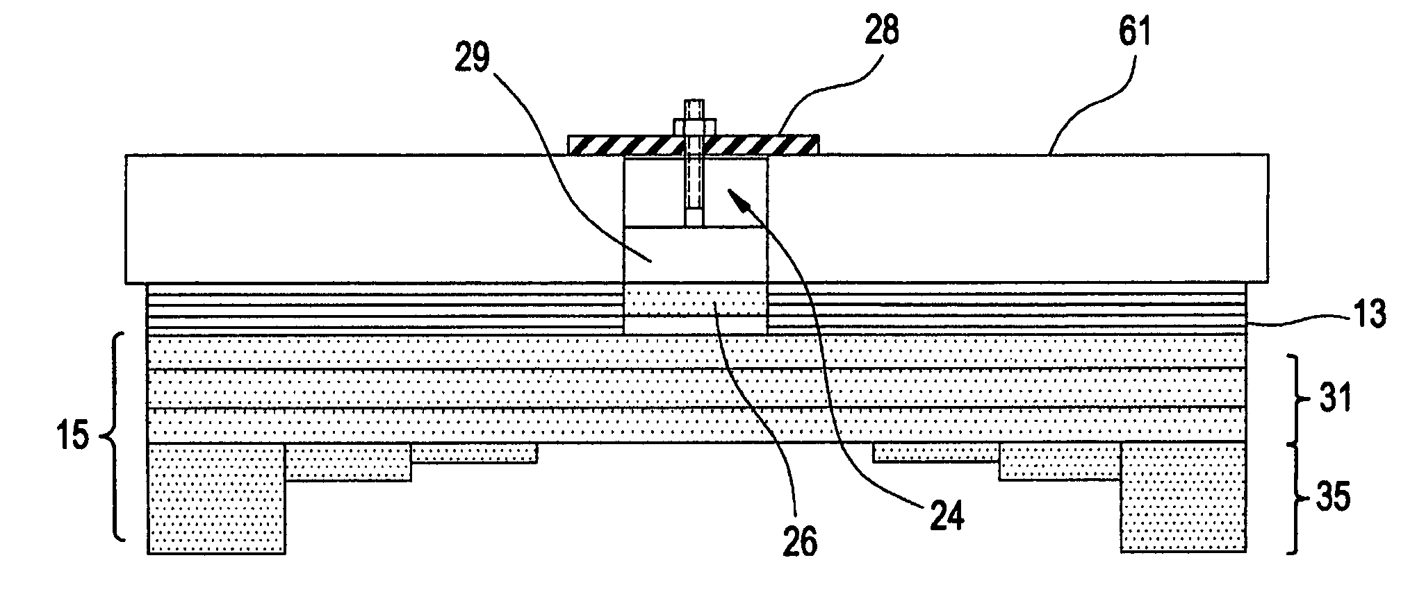
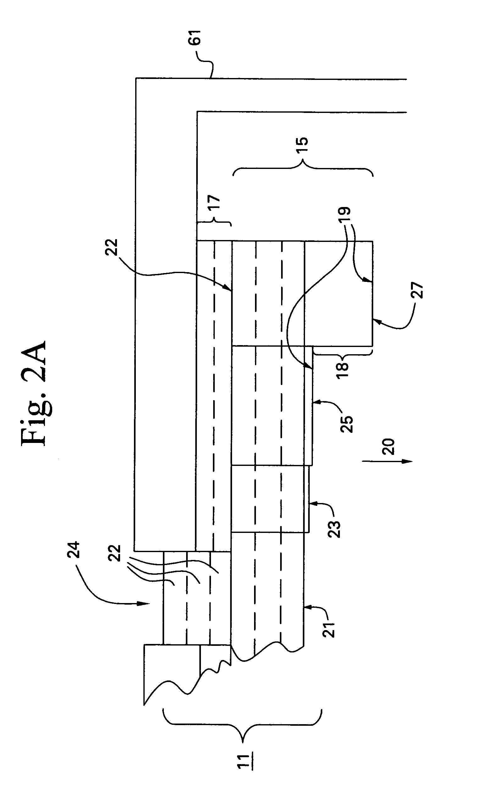
[0022]The present inventors have discovered that a permanent magnet assembly which has a stepped imaging surface having four or more steps and which has a pocket having a depth of at least 0.05 meters filled with metal shims provides an easily shimmed permanent magnet design. Preferably, a hollow ring permanent magnet section of the assembly having a height of at least 0.05 meters forms the rim of the pocket and is assembled separately from a base section of the assembly. The hollow ring section is then attached to the base section of the assembly. The base section may have two or more steps, such as three steps, machined in the exposed portion the imaging surface of the base section.

[0023]Thus, a permanent magnet assembly for an imaging apparatus comprises a permanent magnet body having a first surface and a stepped second imaging surface which is adapted to face an imaging volume of the imaging apparatus. The stepped second surface contains at least four steps. The stepped second ...


PUM

PropertyMeasurementUnit
heightaaaaaaaaaa
depthaaaaaaaaaa
heightaaaaaaaaaa

Abstract

A permanent magnet assembly for an imaging apparatus having a permanent magnet body having a first surface and a stepped second surface which is adapted to face an imaging volume of the imaging apparatus, wherein the stepped second surface contains at least four steps.

Description

BACKGROUND OF THE INVENTION[0001]The present invention is directed generally to permanent magnet assemblies and more particularly to permanent magnet assemblies for MRI systems.[0002]There are various magnetic imaging systems which utilize permanent magnets. These systems include magnetic resonance imaging (MRI), magnetic resonance therapy (MRT) and nuclear magnetic resonance (NMR) systems. MRI systems are used to image a portion of a patient's body. MRT systems are generally smaller and are used to monitor the placement of a surgical instrument inside the patient's body. NMR systems are used to detect a signal from a material being imaged to determine the composition of the material.[0003]These systems often utilize two or more permanent magnets directly attached to a support, frequently called a yoke. An imaging volume is providing between the magnets. A person or material is placed into an imaging volume and an image or signal is detected and then processed by a processor, such a...

Claims


Application Information

Patent Timeline
Patent Type & Authority Patents(United States)
IPC IPC(8): G01V3/00H01F7/02A61B5/055G01R33/383H01F1/057H01F1/147H01F7/128H01F41/02
CPCG01R33/383H01F7/128H01F1/057H01F41/028H01F7/0278H01F1/147
Inventor AMM, KATHLEEN MELANIELASKARIS, EVANGELOS TRIFONTHOMPSON, PAUL SHADFORTHAKSEL, BULENTAMM, BRUCE CAMPBELLPALMO, JR, MICHAEL ANTHONYVAN OORT, JOHANNES MARTINUSHUANG, XIANRUI
Owner GENERAL ELECTRIC CO
Why Eureka
Try Eureka