
Internally-calibrated, two-detector gas filter correlation radiometry (GFCR) system

a gas filter and correlation radiometry technology, applied in the field of two-detector gas filter correlation radiometry (gfcr), can solve the problems of loss of signal integration time, difficult model of signals, severe corruption of difference measurement, etc., and achieve the effect of accurate calibration and easy calibration

Inactive Publication Date: 2008-09-09
G & A TECHN SOFTWARE
View PDF6 Cites 7 Cited by
  • Summary
  • Abstract
  • Description
  • Claims
  • Application Information

AI Technical Summary

Benefits of technology

"The present invention provides a gas filter correlation radiometry (GFCR) system that uses a two-detector methodology and can be accurately calibrated. The system includes an optical train with a calibrating light and a gas cell for detecting the gas of interest. The calibrating light is used to calibrate the system and the light from the selected field-of-view is used to measure the gas of interest. The system is easy to calibrate and can provide accurate results."

Problems solved by technology

Thus, small drifts in detector response, if not detected and corrected, can severely corrupt the difference measurement.
However, because the conventional two-detector method requires continuous high-precision calibration of the balance condition (i.e. calibration of the signal drift due to changes in system response), most researchers have abandoned the two-detector method in favor of single-detector methods.
Unfortunately, while single-detector methods can nearly eliminate detector instability as an error source by measuring both signals with the same detector, they introduce a host of other problems, depending on method of implementation.
The signals are also difficult to model because of gas heating and cell state variation that may not reach uniform equilibrium.
However, both of these approaches introduce noise due to beam steering and loss of signal integration time due to time between modulated states.
An even greater problem with any single-detector method is the loss of measurement simultaneity and / or the ability to exactly match field-of-views for gas and vacuum paths.
If the scene changes during the time necessary to switch between modulated states or because of field-of-view mismatch, the change in normalized difference signal (caused by scene brightness variation) will corrupt the data interpretation that assumes the difference signal is produced solely by spectral variation.
This presents a severe problem for the single-detector method, or any method that does not make simultaneous and spatially identical measurements of the two states (i.e., gas path and vacuum path).

Method used


Image

  • Internally-calibrated, two-detector gas filter correlation radiometry (GFCR) system
  • Internally-calibrated, two-detector gas filter correlation radiometry (GFCR) system
  • Internally-calibrated, two-detector gas filter correlation radiometry (GFCR) system

Examples


Embodiment Construction

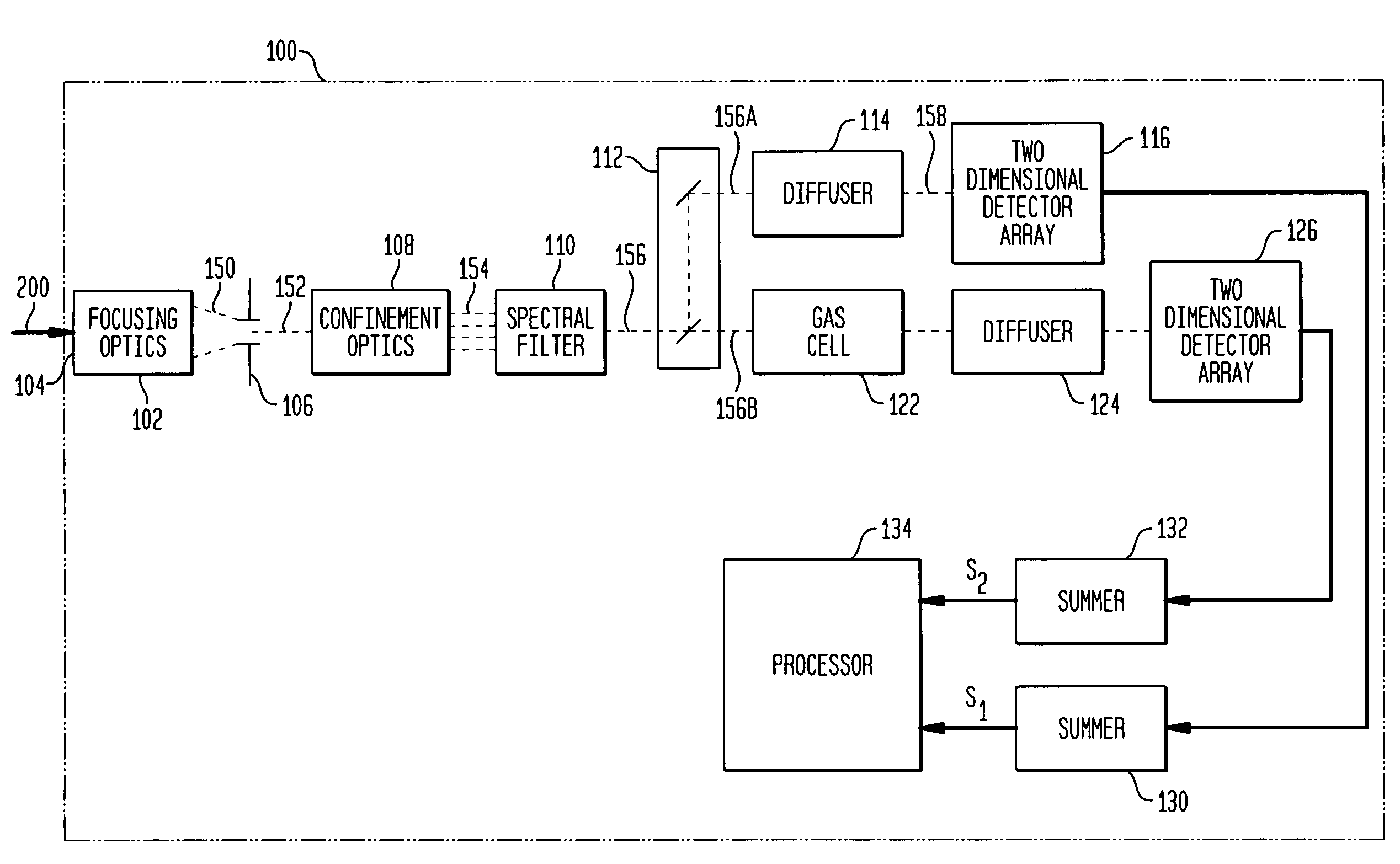
[0031]The present invention is a gas filter correlation radiometry (GFCR) system utilizing a two-detector methodology to simultaneously provide light-absorbing and non-light absorbing measurements without requiring any back-end electronics to balance the system. The system structure also provides for novel approaches to on-board balance calibration and data analysis calibration.

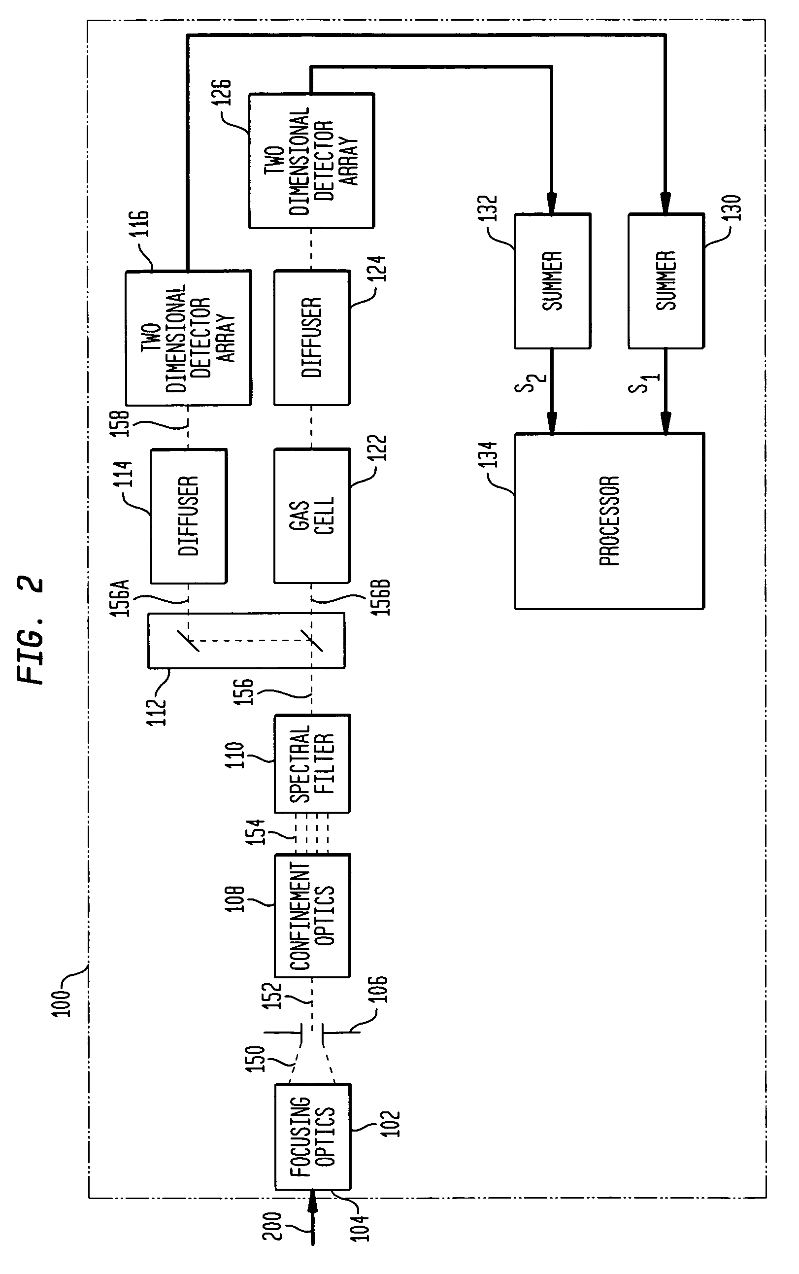
[0032]Referring again to the drawings and more particularly to FIG. 2, a GFCR system in accordance with an embodiment of the present invention is shown and is contained within the dashed-line box referenced by numeral 100. In GFCR system 100, optical signal transmission between elements thereof is indicated by dashed-lines and electrical signal transmission between elements thereof is indicated by solid lines that terminate in an arrowhead.

[0033]GFCR system 100 provides a measurement of a gas of interest or “target gas” by processing an external scene light 200 that defines a scene being imaged some distance ...


PUM

PropertyMeasurementUnit
optical remote sensingaaaaaaaaaa
spectral wavelengthsaaaaaaaaaa
pressureaaaaaaaaaa

Abstract

An entrance aperture of a GFCR system receives light from a scene of interest. The light is focused to form an image at a focal plane. Light associated with a selected field-of-view of the image at the focal plane is then confined to a spectral band at which a gas of interest absorbs. The confined light is split into first and second paths. A calibrating light is selectively produced from within the optical train at the focal plane. A portion of the calibrating light traverses each of the first and second paths. A region that is substantially non-interfering with respect to the spectral band is disposed in the first path. A gas cell filled with the gas of interest is disposed in the second path. The light passed through the region and through the gas cell is independently detected and used to generate output signals indicative of the light so-detected. The output signals are processed with the output signals generated by the light from the selected field-of-view of the image being used to generate a measure of the gas of interest and the output signals generated by the portion of the calibrating light traversing the first and second paths being used to calibrate the GFCR system.

Description

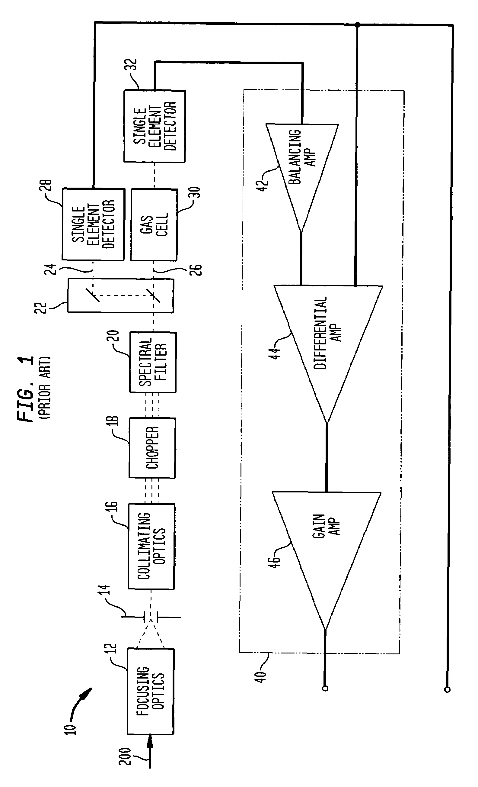
CROSS-REFERENCE TO RELATED PATENT APPLICATIONS[0001]This patent application is co-pending with one related patent application entitled “TWO-DETECTOR GAS FILTER CORRELATION RADIOMETRY (GFCR) SYSTEM USING TWO-DIMENSIONAL ARRAY DETECTION OF DEFOCUSED IMAGE AND DETECTED-SIGNAL SUMMATION”, filed by the same inventor and owned by the same assignee as this patent application.FIELD OF THE INVENTION[0002]The invention relates generally to gas filter correlation radiometry (GFCR), and more particularly to a two-detector GFCR system that includes a controllable internal light-producing source for use in calibrating the GFCR system.BACKGROUND OF THE INVENTION[0003]“Gas filter correlation radiometry” (GFCR) is an optical remote sensing method used to produce highly sensitive measurements of “targeted” gases. A conventional GFCR measurement system using two single-element detectors is shown inFIG. 1 and is referenced generally by numeral 10. The basic elements of GFCR system 10 form an optical tr...

Claims


Application Information

Patent Timeline
Patent Type & Authority Patents(United States)
IPC IPC(8): G01N21/00
CPCG01N21/3504G01N21/314
Inventor GORDLEY, LARRY L.
Owner G & A TECHN SOFTWARE
Learn More