Interferometric optical profiler

Inactive Publication Date: 2008-09-09
LI CHIAN CHIU
View PDF9 Cites 31 Cited by
  • Summary
  • Abstract
  • Description
  • Claims
  • Application Information

AI Technical Summary

Problems solved by technology

The reflected beams are then recombined by the beam splitter and interfere with each other.
The interference results in interference patterns, or intensity distribution on a detector.
The measurement is fast, but is sensitive to vibration since vibration of either the reference mirror or the sample changes the optical path.
Because of vibration, su

Method used


Image

  • Interferometric optical profiler
  • Interferometric optical profiler
  • Interferometric optical profiler

Examples


Embodiment Construction

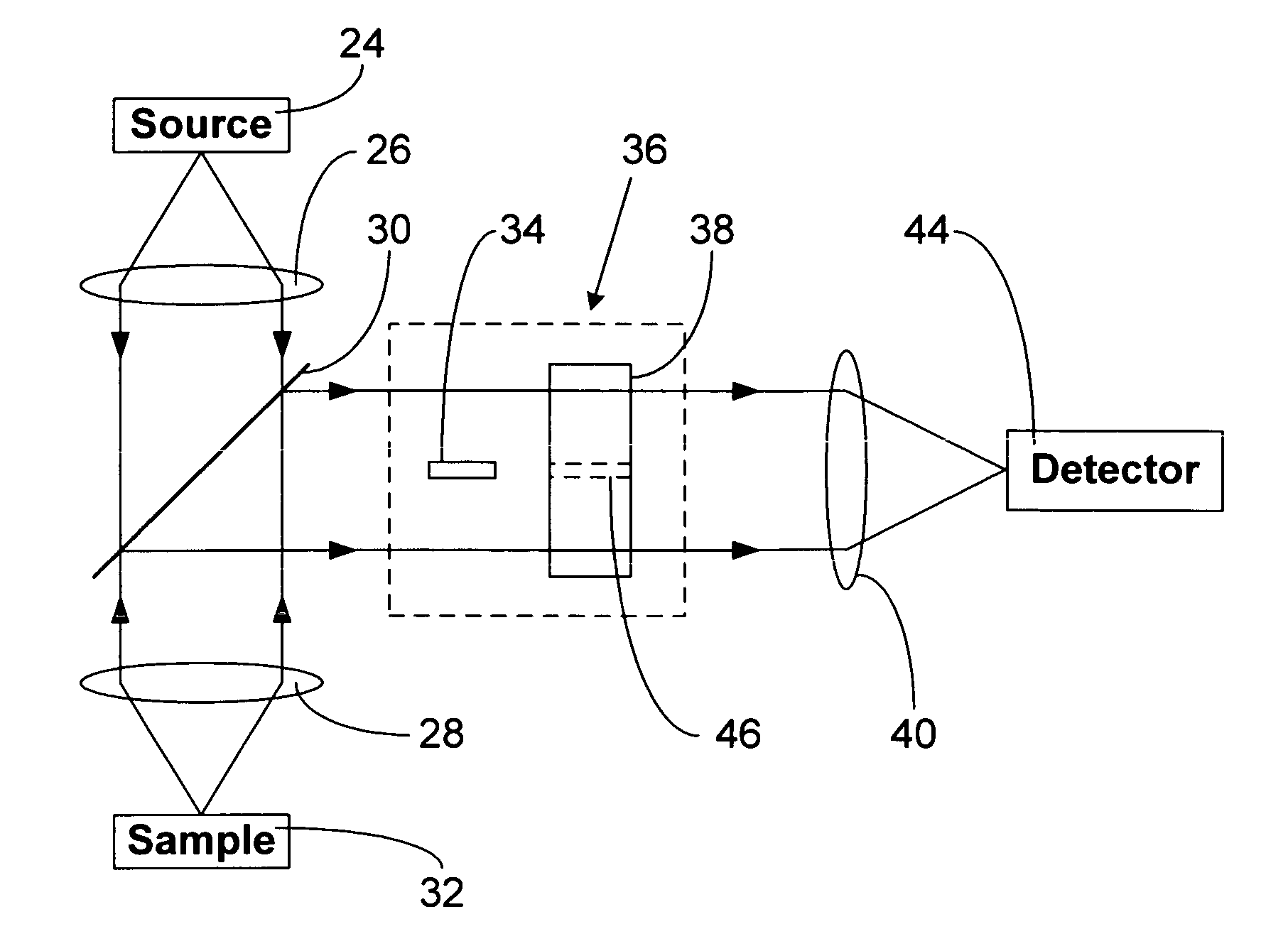
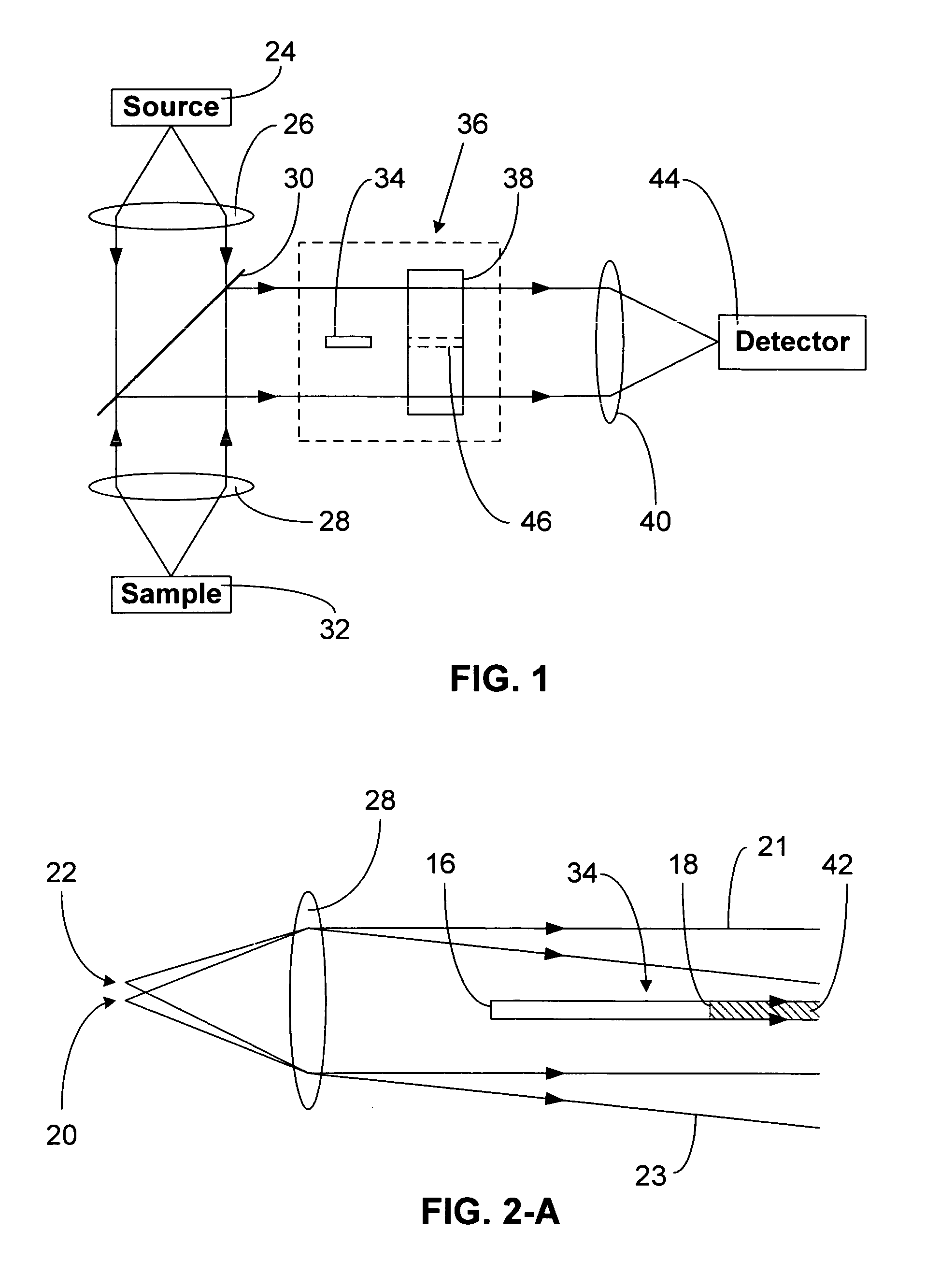
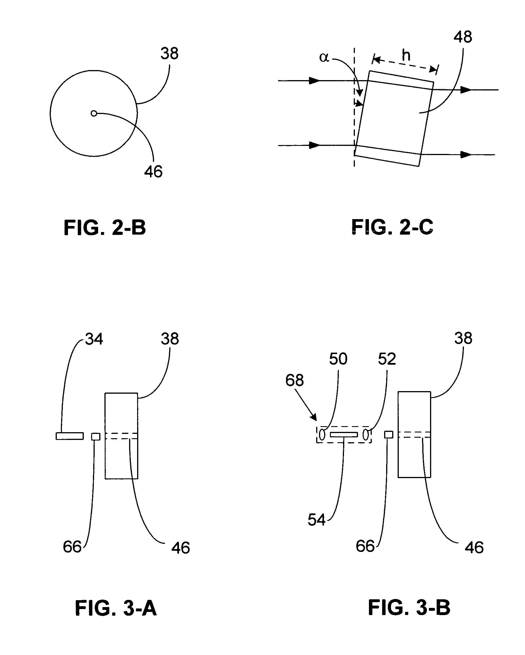
FIG. 1& FIGS. 2-A to 2-C—Interferometric Optical Profiler

[0028]FIG. 1 illustrates schematically an embodiment of the interferometric optical profiler according to the invention. The components used here are individually well known in the field of optics and interferometry. A beam from a light source 24 is collimated by a lens system 26. Source 24 is preferably a single-mode light source, such as a point light source or a single-mode semiconductor laser diode. The collimated beam passes through a beam splitter 30 and is focused by a lens system 28 onto a surface area of a sample 32. The sample may be, e.g., a silicon wafer, a chip of an integrated circuit, or the tip of an optical fiber. The impinging light is then reflected by the surface. The reflected beam is collimated by lens system 28 and reflected by beam splitter 30. The beam splitter has two main types: polarization insensitive and polarization type. The former reflects part of a beam and transmits the other part regardless ...


PUM


Abstract

An imaging-type interferometric optical profiler splits a beam reflected from a sample into two beam portions. One portion is a reference beam and the other a sample beam. The reference and sample beams are combined to create interference patterns which are used to obtain a surface profile of the sample. Since vibration of the sample causes the same optical path change, and no reference mirror is used, the interferometric optical profiler is relatively vibration-insensitive and has a fast measurement speed.

Description

CROSS REFERENCE TO RELATED APPLICATION[0001]This application is entitled to the benefit of Provisional Patent Application Ser. No. 60 / 530,432 filed 2003 Dec. 17.FEDERALLY SPONSORED RESEARCH[0002]Not applicableSEQUENCE LISTING OR PROGRAM[0003]Not applicableBACKGROUND[0004]1. Field of Invention[0005]This invention is related to interferometric optical devices, particularly to interferometric optical profilers used in topography measurement.[0006]2. Description of Prior Art[0007]An interferometric optical profiler is a device which uses optical interference to measure the profile of a sample surface without physical contact. Surface profile measurement is often required in semiconductor, data storage, and fiberoptic telecommunication industries. For example, inspection of a silicon wafer's surface is often performed in the semiconductor industry. There are two major types of interferometric optical profilers: imaging and scanning types.[0008]An imaging type profiler produces an optical...

Claims


Application Information

Patent Timeline
IPC IPC(8): G01B9/02
CPCG01B11/2441G01B9/02057G01B9/02019G01B9/0201
Inventor LI, CHIAN CHIU
Owner LI CHIAN CHIU
Why Eureka
Try Eureka