Optical packet exchanger
a packet exchanger and optical technology, applied in the field of optical packet exchangers, can solve the problems of reducing transmission efficiency and transmittable capacity by the amount, and achieve the effect of preventing the reduction of throughput due to multiplexing of an address signal and high modulation speed of an information signal
- Summary
- Abstract
- Description
- Claims
- Application Information
AI Technical Summary
Benefits of technology
Problems solved by technology
Method used
Image
Examples
first embodiment
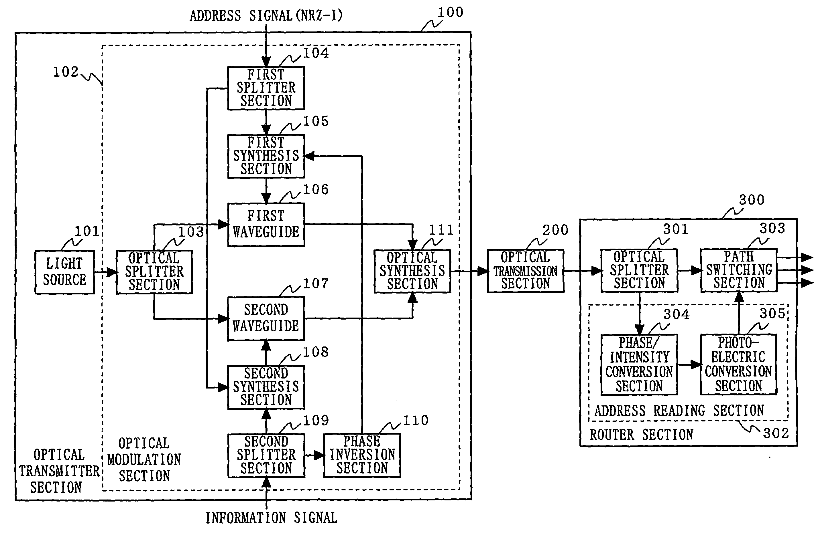
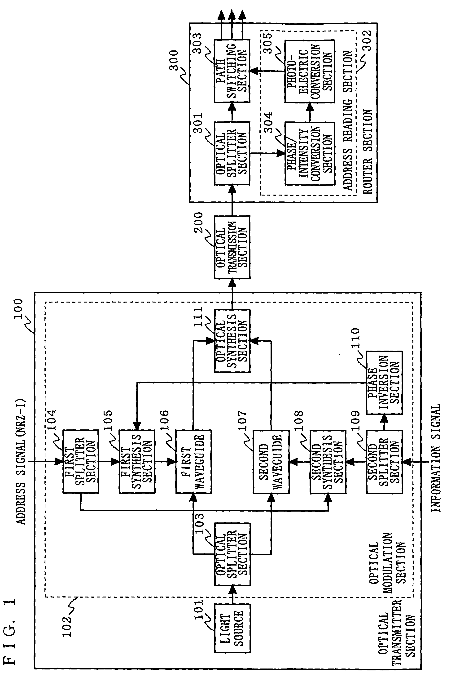
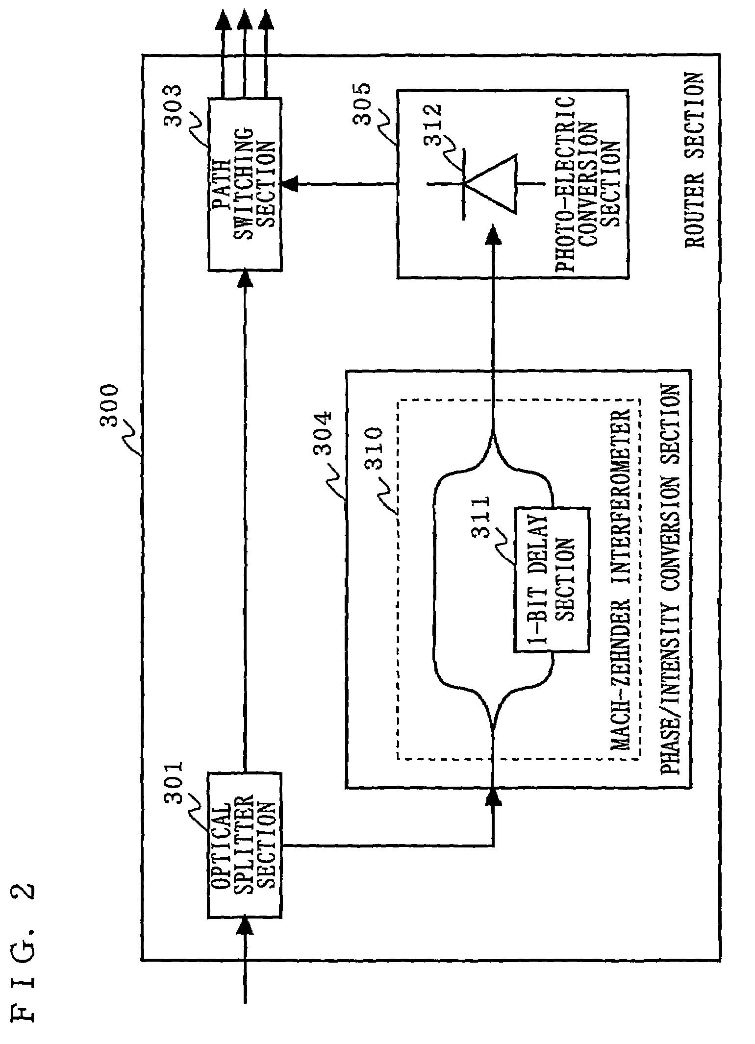
[0028]FIG. 1 is a block diagram illustrating the structure of an optical packet exchanger according to a first embodiment of the present invention. In FIG. 1, the optical packet exchanger according to the first embodiment is composed of an optical transmitter section 100, an optical transmission section 200, and a router section 300. The optical transmitter section 100 comprises a light source 101 and an optical modulation section 102. The optical modulation section 102 includes an optical splitter section 103, a first splitter section 104, a first synthesis section 105, a first waveguide 106, a second waveguide 107, a second synthesis section 108, a second splitter section 109, a phase inversion section 110, and an optical synthesis section 111. The router section 300 comprises an optical splitter section 301, an address reading section 302, and a path switching section 303. The address reading section 302 includes a phase / intensity conversion section 304 and a photoelectric conver...
second embodiment
[0051]FIG. 7 is a block diagram illustrating the structure of an optical packet exchanger according to a second embodiment of the present invention. In FIG. 7, the optical packet exchanger according to the second embodiment is composed of an optical transmitter section 120, an optical transmission section 200, and a router section 300. The optical transmitter section 120 comprises a light signal source 121 and an optical modulation section 122. The light signal source 121 includes a light source 101, a first splitter section 104, a first synthesis section 105, and a first waveguide 106. The optical modulation section 122 includes a second waveguide 107, a second synthesis section 108, a second splitter section 109, and a phase inversion section 110. The router section 300 has the same structure as that of the router section 300 in the first embodiment.
[0052]As seen from FIG. 7, in the optical packet exchanger according to the second embodiment, a phase modulation function using an a...
third embodiment
[0053]FIG. 8 is a block diagram illustrating the structure of an optical packet exchanger according to a third embodiment of the present invention. In FIG. 8, the optical packet exchanger according to the third embodiment includes an optical transmitter section 130, an optical transmission section 200, and a router section 300. The optical transmitter section 130 comprises a light signal source 131 and an optical modulation section 132. The light signal source 131 includes a light source 101, a second waveguide 107, a second synthesis section 108, a second splitter section 109, and a phase inversion section 110. The optical modulation section 132 includes a first splitter section 104, a first synthesis section 105, and a first waveguide 106. The router section 300 has the same structure as that of the router section 300 in the first embodiment.
[0054]As seen from FIG. 8, in the optical packet exchanger according to the third embodiment, a phase modulation function using an address si...
PUM
 Abstract
Description
Claims
Application Information
 - R&D
- Intellectual Property
- Life Sciences
- Materials
- Tech Scout
- Unparalleled Data Quality
- Higher Quality Content
- 60% Fewer Hallucinations
Browse by: Latest US Patents, China's latest patents, Technical Efficacy Thesaurus, Application Domain, Technology Topic, Popular Technical Reports.
© 2025 PatSnap. All rights reserved.Legal|Privacy policy|Modern Slavery Act Transparency Statement|Sitemap|About US| Contact US: help@patsnap.com


