Brake pad with wear indicator

a technology of wear indicators and brake pads, applied in the field of brake pads, can solve problems such as catastrophic danger and damage, erode expensive parts, and disturb brakes

Inactive Publication Date: 2008-09-16
MCCLELLAN WILLIAM THOMAS
View PDF11 Cites 55 Cited by
  • Summary
  • Abstract
  • Description
  • Claims
  • Application Information

AI Technical Summary

Benefits of technology

[0020]It is accordingly an object of the invention to provide a brake pad with a wear indicator, which overcomes the hereinafore-mentioned disadvantages of the heretofore-known devices of this general type and which provides a simple, reliable, effective, failsafe, clear to the untrained, low maintenance, all wheel, direct measuring, contrasting color brake wear indicator. It is understood that all of the details of the brake pad apply equally to a bake shoe as well and that the term pad is used herein to encompass a shoe as well.
[0025]In accordance with an additional feature of the invention, the friction material layer has a lateral extent and a vertical extent, as well as outer and inner regions and upper and lower regions. The inner layers are disposed in an outer 50% of the lateral extent and in a lower 30% of the vertical extent. In this way, slowly increasing amounts of wear-indicating colored brake dust will appear.

Problems solved by technology

It is in the process of using up the friction material that braking is disturbed and catastrophic danger and damage occur.
Wear-through of the brake pads can create an emergent brake failure and the resultant metal-to-metal contact can erode expensive parts.
Brake pads suffer extremes in mechanical forces and temperatures.
Thin metal noise makers (blades or springs mounted on the pads) are only mounted on front brakes and have limited use because they are not used on rear wheels, trailers, buses, large trucks, construction equipment or airplanes.
They not only suffer that inaccuracy, but lack reliability and increased maintenance, inherent to their complexities of gears, cams, followers, pins, contacts, electric wires, circuit breakers and lights.
They are especially failure prone in the hostile environment of the exposed wheel location, with high “G” loads, vibrations of the bouncing wheels and exposure to dirt, water, ice and road salt.
None of the prior art provides a self-test or failure warning.
Wear through, brake failure and extreme repair costs are still common.
The prior art homogeneous colored layer is not failsafe but instead is failure prone.
Two dangerous structural faults are present.
The tremendous shear forces of braking are inline with this soft fault line, so that pad separation results and total brake failure occurs.
The homogeneous layering of soft, smooth non-friction particles also causes a sudden loss of brake efficiency once the colored layer is uncovered.
The colored particles instantly coat the exposed layer with an ineffective surface of minimal friction.
This soft substance acts as a lubricant, as braking friction suddenly drops and brake failure occurs.
A homogeneous colored layer used as a brake wear indicator is flawed and unacceptable.

Method used


Image

  • Brake pad with wear indicator
  • Brake pad with wear indicator
  • Brake pad with wear indicator

Examples


Embodiment Construction

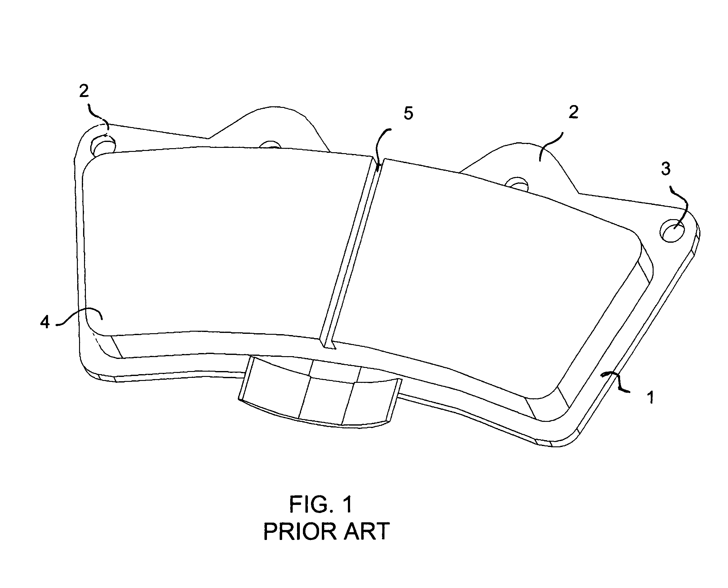
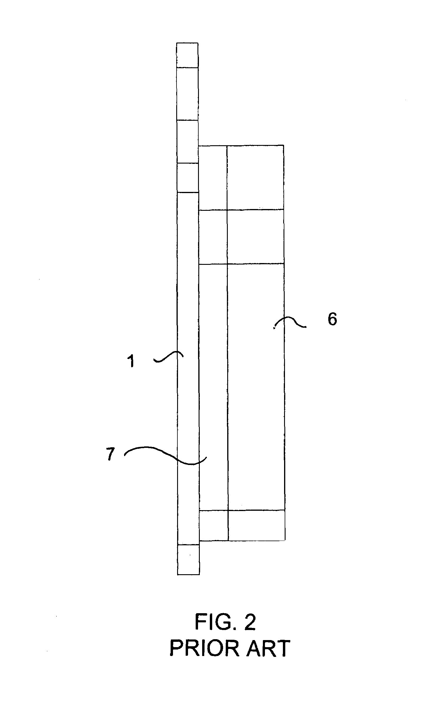
[0040]Referring now in detail to the figures of the drawing, in which the same reference numerals have been used for similar features, and first, particularly, to FIG. 1 thereof, there is seen a prior art brake pad having a backing plate 1 with lugs 2 in which mounting holes 3 are formed. A friction material layer 4 is attached to the backing plate 1 for pressing against a rotor or drum. The friction material layer 4 is formed of a strong matrix of tough aramid fibers, rock-hard, sharp-edged, friction particles and heat-resistant hardening resin, which are specially provided for an environment encountering extremes in mechanical forces and temperatures. The integrity of the layer depends on a uniform cohesiveness throughout the layer and strong attachment to the backing plate.

[0041]A groove 5 is cut into the friction material layer 4 to indicate the wear level. Holes may also be formed in the friction material layer to provide the same wear level indication function. The wear at suc...


PUM


Abstract

A brake pad includes a backing plate and a friction material layer attached to the backing plate. At least one inner layer is disposed within the friction material layer. The inner layer has a color different than the friction material layer.

Description

BACKGROUND OF THE INVENTION[0001]1. Field of the Invention[0002]The invention relates to a brake pad with a backing plate, a friction material layer and a wear indicator.[0003]2. Description of the Related Art[0004]All modern ground transportation, that is motorcycles, bicycles, automobiles, trucks, construction equipment and even airplanes during taxi, takeoff and landing, control deceleration by converting the vehicle's kinetic energy or mass velocity, into heat by a system of friction braking.[0005]Generally a pad and a rotor or a shoe and a drum configuration are used. The pad or shoe (made of a special friction absorbing material) is connected to the vehicle, and is pressed against a metal rotor or drum attached to the rotating axle or wheel. As the friction part is pressed against the rotating part, energy is absorbed, and the vehicle decelerates.[0006]The friction material is constructed to maximize strength, friction co-efficient and heat tolerance, but not be so hard, hot, ...

Claims


Application Information

Patent Timeline
Patent Type & Authority Patents(United States)
IPC IPC(8): F16D66/02
CPCF16D66/028F16D2069/005
Inventor MCCLELLAN, WILLIAM THOMAS
Owner MCCLELLAN WILLIAM THOMAS
Why Eureka
Try Eureka