
Electromagnetic acoustic transducers for use in ultrasound inspection systems

a technology of acoustic transducers and ultrasound, applied in the field of ultrasound inspection systems, can solve the problems of inability to propagate acoustic waves, inability to use the coupling medium between the transducer and the specimen, and the emats typically have greatly reduced the transduction efficiency compared with acoustically coupled transducers

Active Publication Date: 2008-09-23
GENERAL ELECTRIC CO +1
View PDF23 Cites 14 Cited by
  • Summary
  • Abstract
  • Description
  • Claims
  • Application Information

AI Technical Summary

Benefits of technology

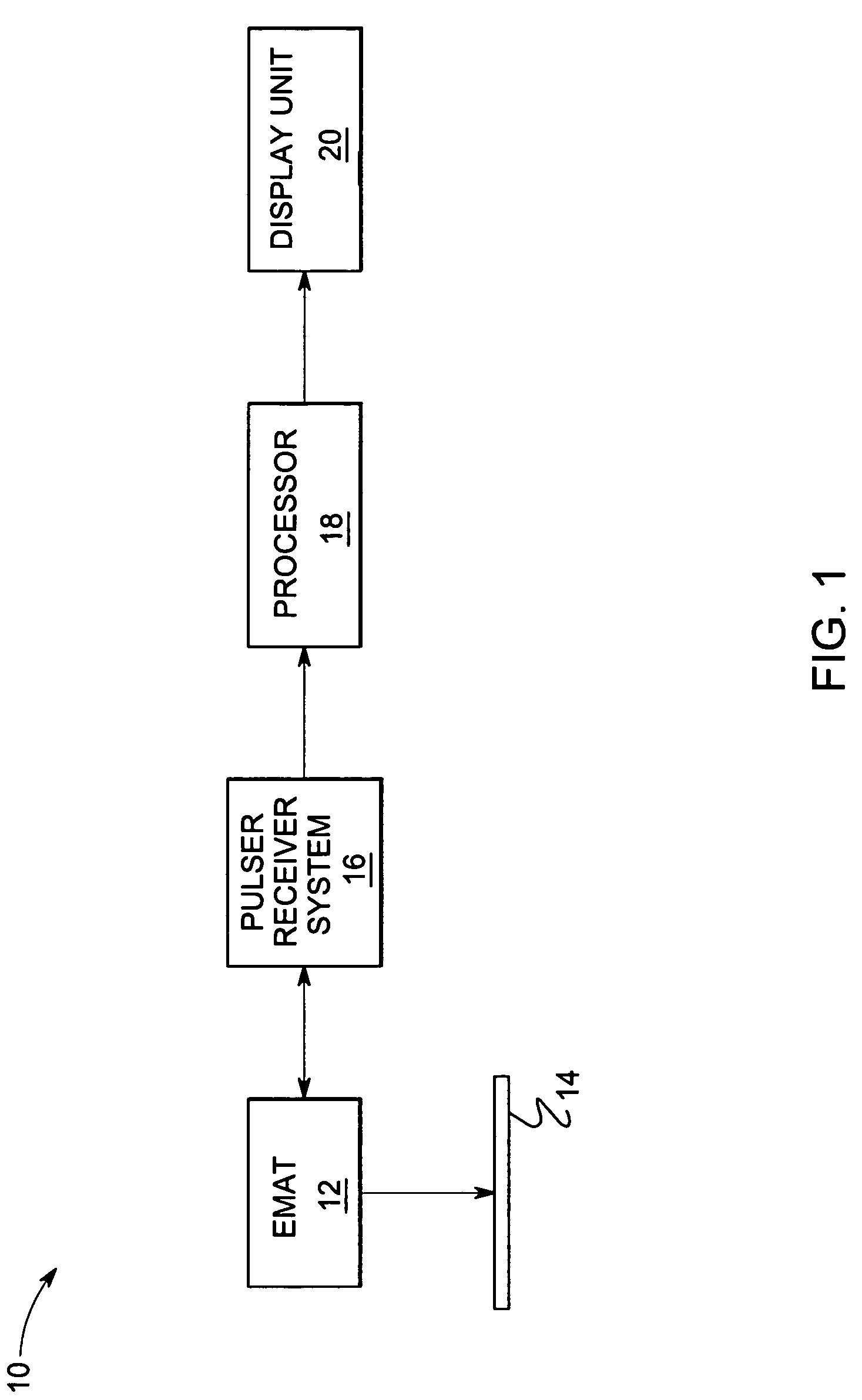
The invention is an ultrasound system that uses an electromagnetic acoustic transducer (EMAT) to inspect objects. The EMAT generates acoustic signals by transmitting a magnetic field and applying a radio frequency (RF) pulse to the object. The system includes a pulser-receiver system that converts the acoustic signals to electrical signals. The technical effect of this invention is that it provides a non-destructive method for inspecting areas of objects using ultrasound without the need for a physical contact between the inspector and the object.

Problems solved by technology

The absence of a coupling medium enables EMAT transducers to be used in a variety of applications where the use of the coupling medium between the transducer and the specimen is either impractical or undesirable.
For example, if the specimen is coated with an acoustically attenuating material, acoustic wave propagation is not feasible.
EMATs typically have greatly reduced transduction efficiency compared with acoustically coupled transducers.
Thus, they are not generally adaptable for use with existing ultrasonic inspection equipment such as ultrasound (UT) pulser-receivers or flaw detectors.
However, these systems typically generate low-bandwidth signals compared to conventional UT pulser-receivers, which limit inspection resolution.
Such an arrangement causes parasitic eddy currents to be induced in the magnet thus causing the RF field to cancel out rapidly when the EMAT is lifted off from the object's surface thus reducing the lift-off performance of the probe.
The close proximity of the RF coil and the magnet also decreases the transduction efficiency of the transducer.

Method used


Image

  • Electromagnetic acoustic transducers for use in ultrasound inspection systems
  • Electromagnetic acoustic transducers for use in ultrasound inspection systems
  • Electromagnetic acoustic transducers for use in ultrasound inspection systems

Examples


Embodiment Construction

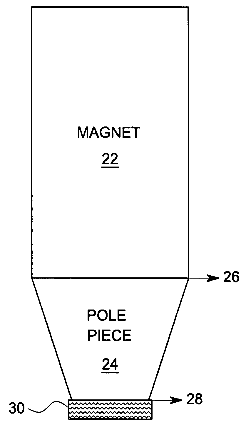
[0014]FIG. 1 is a block diagram of one embodiment of an ultrasound inspection system used to inspect an object. The ultrasound inspection system 10 implements an electromagnetic acoustic transducer (EMAT) in conjunction with a pulser receiver system to inspect the object. Each block is explained in further detail below.

[0015]As used herein, “adapted to”, “configured” and the like refer to devices in a system to allow the elements of the system to cooperate to provide a described effect; these terms also refer to operation capabilities of electrical or optical elements such as analog or digital computers or application specific devices (such as an application specific integrated circuit (ASIC)), amplifiers or the like that are programmed to provide an output in response to given input signals, and to mechanical devices for optically or electrically coupling components together.

[0016]Electromagnetic acoustic transducer (EMAT) 12 is configured to generate acoustic signals representativ...


PUM

PropertyMeasurementUnit
areaaaaaaaaaaa
static magnetic fieldaaaaaaaaaa
electrically non-conductiveaaaaaaaaaa

Abstract

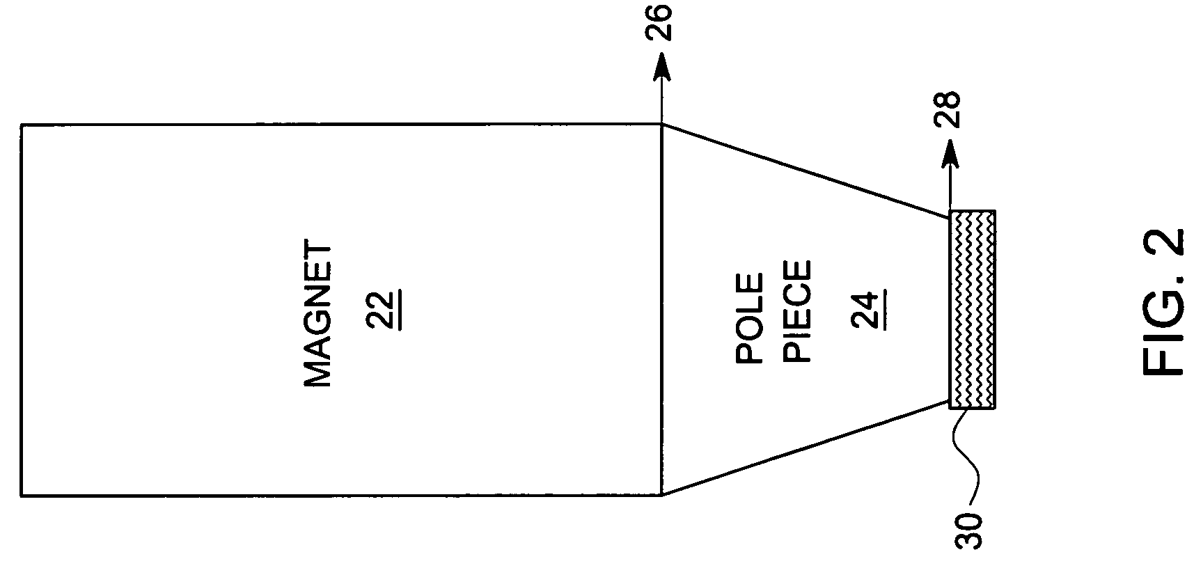
An ultrasound system for inspecting an object is provided. The ultrasound system includes an electromagnetic acoustic transducer (EMAT) and a pulser-receiver system. The EMAT is configured to generate acoustic signals representative of the area being inspected and comprises a flux concentrating non-conductive pole piece separating a radio frequency (RF) coil and a magnet. The pulser-receiver system is coupled to the EMAT and configured to receive the acoustic signals and convert the acoustic signal to electrical signals.

Description

BACKGROUND[0001]The invention relates generally to inspection systems and more specifically to electromagnetic acoustic transducers for use in ultrasound systems.[0002]Ultrasonic inspection is a commonly used non-destructive evaluation (NDE) technique for detecting corrosion and cracking in different objects such as metallic components, pipes, etc. Electromagnetic acoustic transducers (EMATs) are ultrasonic transducers that couple acoustic energy into and out of an object electromagnetically rather than through the use of an acoustic coupling medium such as water.[0003]An EMAT generates ultrasonic energy in a conductive sample under test as follows. A magnetic field is applied to the sample using a magnet, and radio frequency (RF) eddy-currents are induced into the sample using a RF coil. The RF pulse interacts with the magnetic field to produce a mechanical force, which in turn produces ultrasonic waves at the radio frequency.[0004]The absence of a coupling medium enables EMAT tran...

Claims


Application Information

Patent Timeline
Patent Type & Authority Patents(United States)
IPC IPC(8): G01N9/24G01N27/72
CPCB06B1/04G01N29/2412G01N2291/0422
Inventor KOCH, ROMAN HEINRICHMAY, ANDREWLI, JIAN
Owner GENERAL ELECTRIC CO
Learn More