Scavenging carburetor

a scavenging carburetor and butterfly-type technology, which is applied in the field of carburetors, can solve the problems of not allowing a favorable relationship between conventional carburetor valve arrangements and the use of butterfly-type scavenging valves, and achieving the effect of improving the relationship

Active Publication Date: 2008-09-30
WALBRO LLC
View PDF7 Cites 6 Cited by
  • Summary
  • Abstract
  • Description
  • Claims
  • Application Information

AI Technical Summary

Benefits of technology

[0009]A scavenging carburetor with an improved relationship between opening properties of a throttle valve and a scavenging valve. The throttle valve includes a butterfly valve that opens and closes a fuel-and-air mixture passage, and the scavenging valve includes a plug-type valve that opens and closes a scavenging air passage. The scavenging carburetor also includes a synchronizing mechanism provided between the throttle valve and scavenging valve to properly synchronize opening and closing of the two valves.
[0010]According to a preferred aspect, an axis of rotation of a support shaft of the butterfly throttle valve extends parallel to an axis of rotation of the plug-type scavenging valve, wherein the valves can be operated smoothly, for instance by using the synchronizing mechanism for connecting the valves. According to another preferred aspect, the scavenging valve may be adapted to start opening the scavenging air passage after the scavenging valve has rotated through a prescribed angle in a fully closed position, so as to essentially totally prevent the supply of scavenging air over a small opening angle range from idle of the throttle valve.
[0014]At least some of the objects, features and advantages that may be achieved by at least certain forms or embodiments of the invention include providing a carburetor that delivers to a combustion chamber of an engine a desired fuel-and-air mixture over a wide range of operating conditions including starting, warming up, and idle, of the engine as well as from idle to wide-open-throttle engine operation, provides an enriched fuel-and-air mixture to an engine combustion chamber to facilitate engine starting, provides a compact carburetor that includes a scavenging air passage, prevents delivery of scavenging air to an engine during engine starting and idle, enables relative movement between a throttle valve and a scavenging valve during at least a portion of throttle valve operation, uses a butterfly throttle valve and a rotary plug-type scavenging valve, minimizes or prevents scavenging air flow in a low speed range of the engine to achieve stable low speed operation and stable acceleration from idle, provides over a high speed range of the engine a relatively small change rate of opening area of the butterfly throttle valve compared to a relatively large change rate of the opening area of the plug-type scavenging valve, is of relatively simple design and economical manufacture and assembly, rugged, durable, reliable and in service has a long useful life.

Problems solved by technology

Using conventional butterfly valve constructions and configurations, it is possible to prevent flow of scavenging air over a low speed range of the engine to achieve stable idle and low speed operation and stable initial acceleration, but there remains a problem during high speed operation.
Specifically, over a high speed range of the engine, use of the butterfly-type scavenging valve does not enable a relatively large rate of change of the opening area of the butterfly-type scavenging valve compared to a relatively small rate of change of the opening area of the butterfly throttle valve.
In short, conventional carburetor valve arrangements do not allow a favorable relationship between the opening areas of the throttle valve and scavenging valve to be achieved so as to meet different needs of a scavenged internal combustion engine operating at different speed and load conditions.

Method used


Image

  • Scavenging carburetor
  • Scavenging carburetor
  • Scavenging carburetor

Examples


Embodiment Construction

First Form

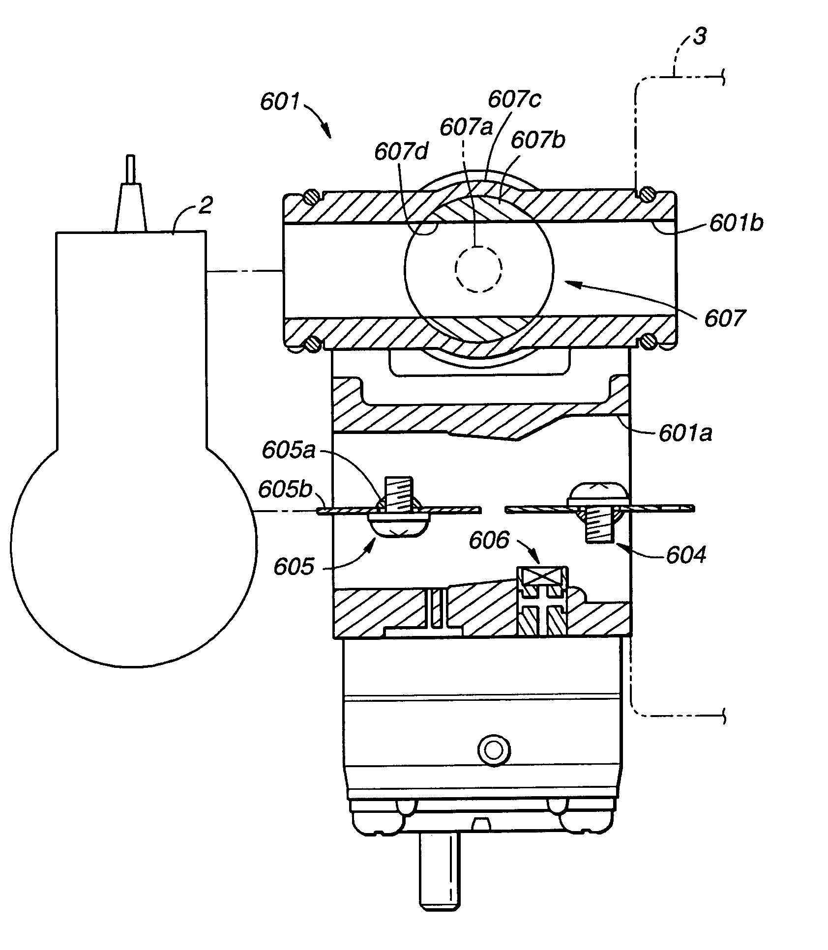
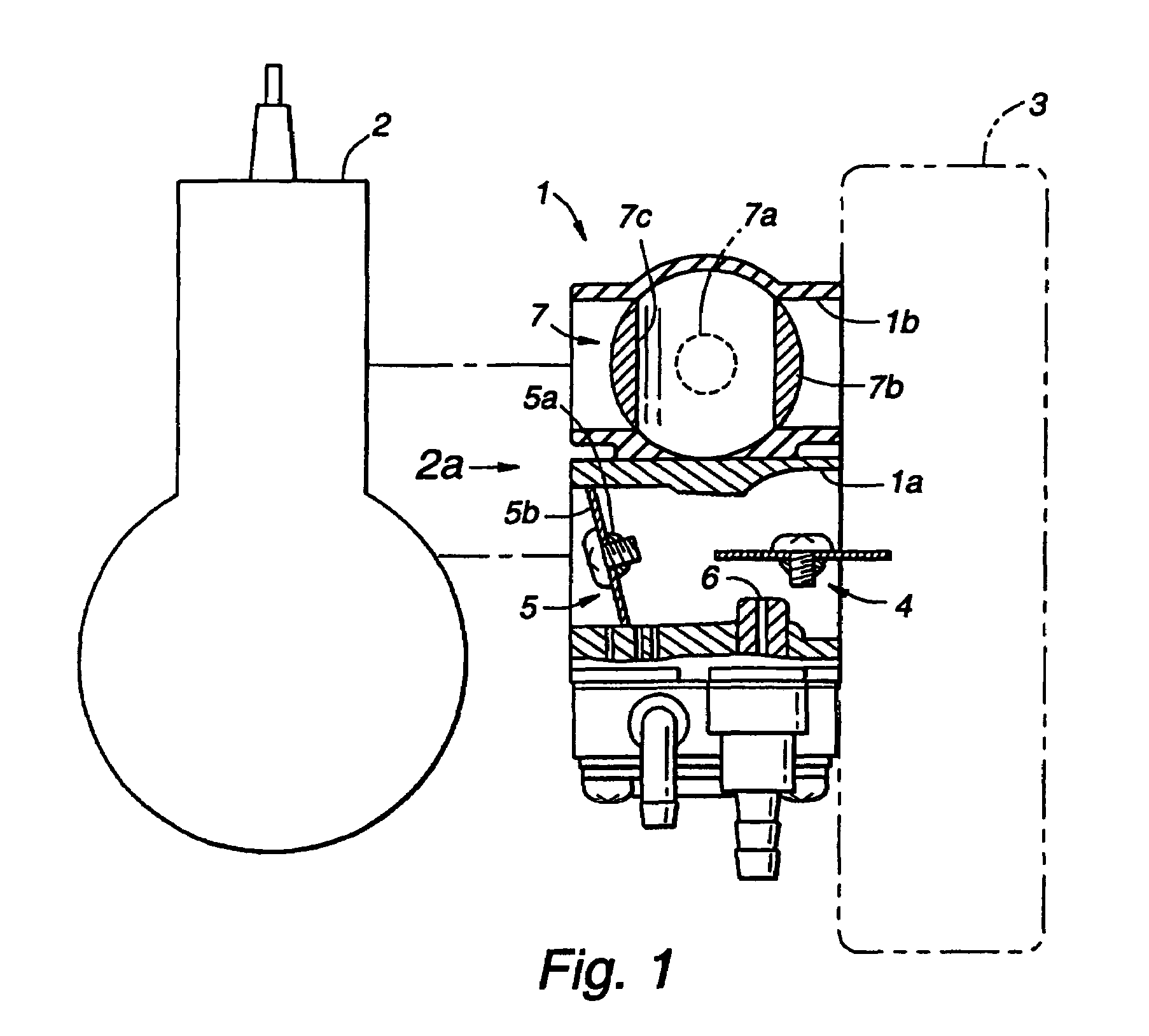
[0058]Referring in more detail to the drawings, FIG. 1 illustrates a presently preferred first form of a scavenging carburetor 1 for use with an air scavenged two-stroke internal combustion engine 2. The carburetor 1 preferably includes a two-piece body including a main body with a fuel-and-air mixture passage 1a for supplying a fuel-and-air mixture to the engine 2, and a separate scavenging body carried by the main body with a scavenging air passage 1b for delivering scavenging air to the engine 2. The passages 1a, 1b are spaced apart and extend generally parallel to each other, and the upstream ends thereof preferably communicate with an air cleaner 3.

[0059]The carburetor 1 also includes various valves for controlling fluid flow therethrough. A choke valve 4 is carried by the main body and disposed within the mixture passage 1a adjacent an upstream end thereof, and a throttle valve 5 is also carried by the main body and disposed within the mixture passage 1a adjacent a d...


PUM

PropertyMeasurementUnit
opening angleaaaaaaaaaa

Abstract

A scavenging carburetor having an improved relationship between scavenging air flow and fuel-and-air flow to an engine over its range of operating conditions. The carburetor has a butterfly throttle valve and a plug-type scavenging valve. Levers are attached to support shafts of the valves and are connected to each other by a connecting rod so as to synchronize movement of the valves. Because of the different opening angle versus open area properties of the two valves, the supply of the scavenging air is minimized over a low speed range of the engine so as to achieve a stable low speed operation and a stable acceleration from idle conditions and a relatively large amount of scavenging air is supplied over a high speed range of the engine for the given amount of fuel-and-air mixture that is supplied. Therefore, the fuel-and-air mixture supply and scavenging air supply is better matched to the requirements of a particular engine than was possible with conventional combinations of valves.

Description

CROSS-REFERENCE TO RELATED APPLICATION[0001]Applicants claim priority of Japanese Application, Ser. No. 2004-357864, filed Dec. 10, 2004; Japanese Application, Ser. No. 2005-229109, filed Aug. 8, 2005; Japanese Application, Ser. No. 2005-232120, filed Aug. 10, 2005; and Japanese Application, Ser. No. 2005-244352, filed Aug. 25, 2005.FIELD OF THE INVENTION[0002]The present invention relates generally to carburetors and more particularly to stratified scavenging carburetors for controlling delivery of a fuel-and-air mixture and scavenging air to an engine.BACKGROUND OF THE INVENTION[0003]In general, carburetors are useful for small two-stroke internal combustion engines commonly used in hand held power tools such as chain saws, weed trimmers, leaf blowers, and the like. Carburetors control engine power by metering and mixing liquid fuel with air to adjust a fuel-to-air ratio and quantity according to varying engine requirements during startup, idle, steady-state operation, and for cha...

Claims


Application Information

Patent Timeline
Patent Type & Authority Patents(United States)
IPC IPC(8): F02M23/03
CPCF02B25/22F02B33/30F02M23/03F02M17/34Y02T10/146Y02T10/12Y10S261/01
Inventor SEKI, HARUNORIDOUYAMA, YOSHIAKITAKAHASHI, TOSHIMASA
Owner WALBRO LLC
Why Eureka
Try Eureka