Method and apparatus for maintaining emission capabilities of hot cathodes in harsh environments

a technology of ionization gauge and hot cathode, which is applied in the direction of instruments, fluid pressure measurement, gas-filled discharge tubes, etc., can solve the problems of reducing the overall operational life of the hot cathode ionization gauge, degrading the emission characteristics of the gauge's cathode, and even destroying the electron emission characteristics of the cathode. , to achieve the effect of increasing the overall operational life of the hot cathod

Active Publication Date: 2008-09-30
MKS INSTR INC
View PDF14 Cites 11 Cited by
  • Summary
  • Abstract
  • Description
  • Claims
  • Application Information

AI Technical Summary

Benefits of technology

[0010]An example method of measuring a gas pressure from gas molecules and atoms according to one embodiment further increases the overall operational lifetime of a hot-cathode ionization gauge by heating at least one cathode to a first temperature to generate electrons and heating at least one other cathode to a second temperature less than the first temperature. The electrons impact gas molecules and atoms to form ions in an anode volume. The ions are then collected to provide an indication of the gas pressure.
[0014]The control circuitry may heat the at least one spare cathode to a temperature that is sufficient to decrease the amount of material that deposits on its surface or is optimized to decrease the chemical interaction between a process gas and a material of the at least one spare cathode. In one embodiment, the control circuitry may heat the at least one emitting cathode to a temperature that decreases the electron emission current emitted from the at least one emitting cathode, to reduce sputtering, when a process pressure passes a given pressure threshold. In another embodiment, the at least one spare cathode and the at least one emitting cathode may both be heated to a temperature that is insufficient to emit electrons from the cathodes when a process pressure passes a given pressure threshold or the ionization gauge turns off.
[0015]In another embodiment, the control circuitry heats at least two cathodes (e.g., an emitting cathode and a spare cathode) to a temperature that is sufficient to emit electrons from the at least two cathodes. In this manner, a spare cathode may be protected from the coating and poisoning processes. At the same time, the spare cathode and an emitting cathode together may provide sufficient electron emission current.
[0016]In yet another embodiment, plural cathodes may be heated to a first temperature to generate electrons. After a process pressure passes a given pressure threshold, the plural cathodes may be heated to a second temperature less than the first temperature. Ions formed by impact between the electrons and the gas atoms and molecules may be collected both before and after the process pressure passes the given pressure threshold. The plural cathodes may be heated to the second temperature to provide a lower electron emission current, for example, between 1 μA and 90 μA. The plural cathodes may also be heated to the second temperature to reduce sputtering of ion gauge components.

Problems solved by technology

However, these same gauges fail in hours or even minutes when operated at high pressures or in gas types that degrade the emission characteristics of the gauge's cathodes.
In this manner, the electron emission characteristics of the cathodes are degraded and even destroyed.
In the poisoning process, the emitting material of the gauge's cathodes may chemically react with gasses from a process occurring in a vacuum chamber so that the emitting material no longer readily emits electrons.
However, in some applications, the electron emitting surface of the cathodes not being used can become poisoned and / or coated by a process.
As a result, the ionization gauge control circuitry may turn off if it cannot cause the cathode to generate a desired electron emission current.

Method used


Image

  • Method and apparatus for maintaining emission capabilities of hot cathodes in harsh environments
  • Method and apparatus for maintaining emission capabilities of hot cathodes in harsh environments
  • Method and apparatus for maintaining emission capabilities of hot cathodes in harsh environments

Examples


Embodiment Construction

[0022]A description of preferred embodiments of the invention follows.

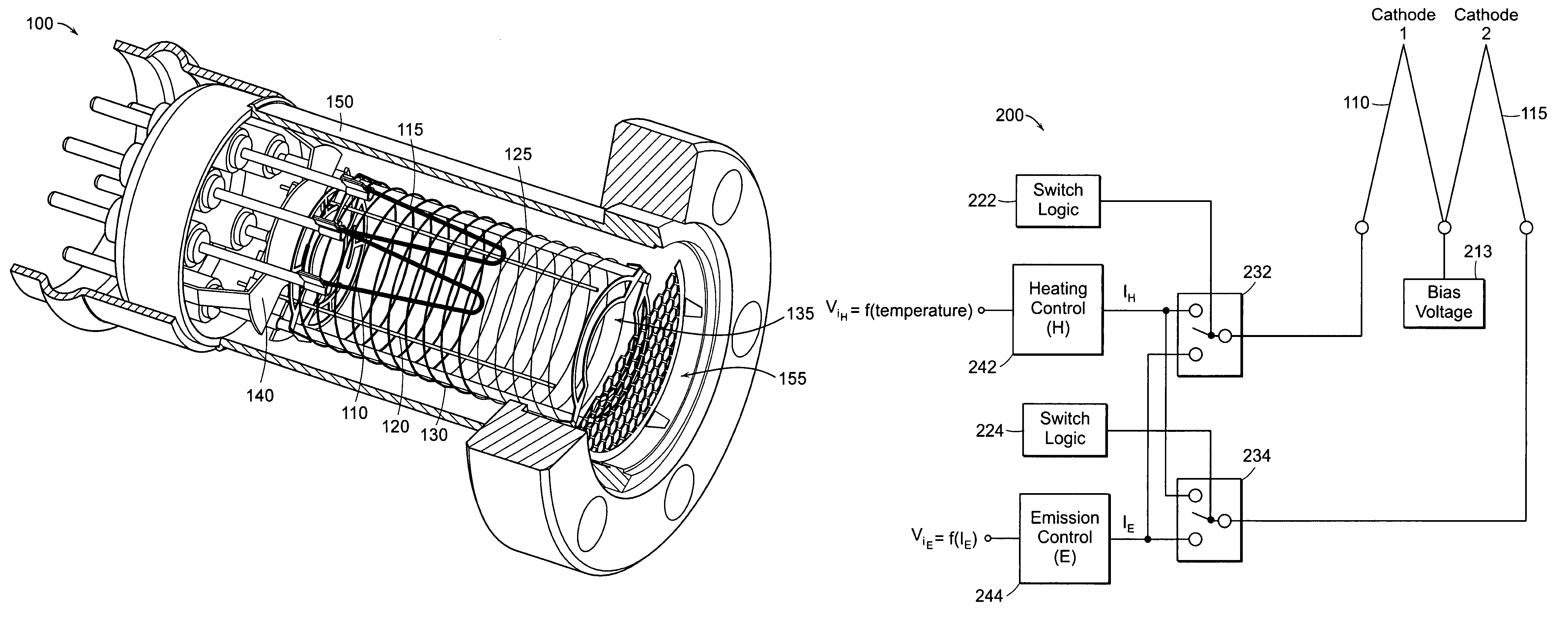
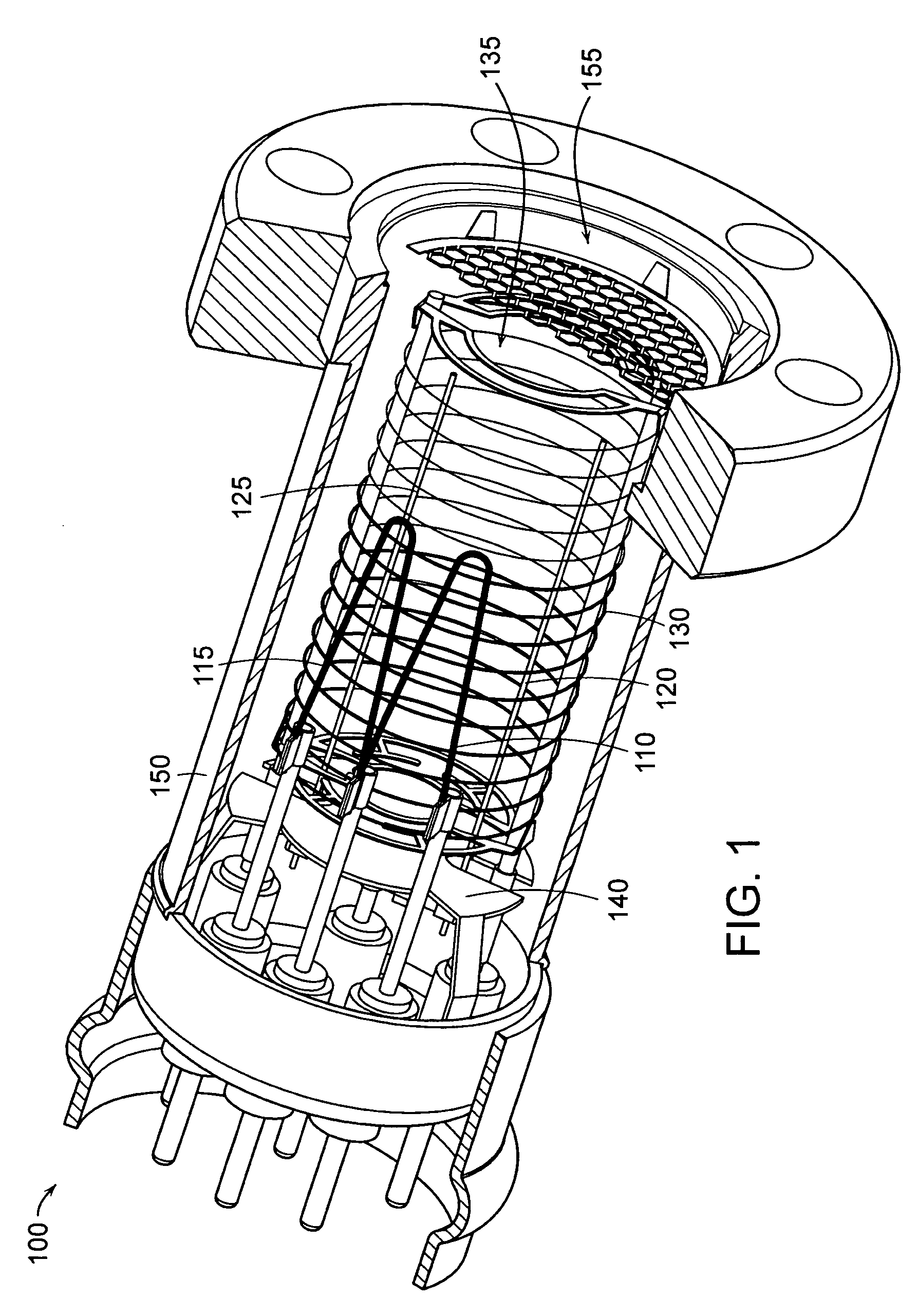
[0023]FIG. 1 is a perspective view of a hot-cathode ionization gauge 100 employing two cathodes 110, 115 according to one embodiment. The hot-cathode ionization gauge 100 includes a cylindrical wire grid 130 (i.e., anode) defining an ionization volume 135 (i.e., anode volume). Two collector electrodes 120, 125 are disposed within the ionization volume 135 and the two cathodes 110, 115 are disposed external from the cylindrical wire grid 130. The above elements of the hot-cathode ionization gauge 100 are enclosed within a tube or envelope 150 that opens into a process chamber via port 155. The hot-cathode ionization gauge 100 also includes a shield 140, such as a stainless steel shield, to shield various electronics components of the ionization gauge from ionized process gas molecules and atoms and other effects of charged particles.

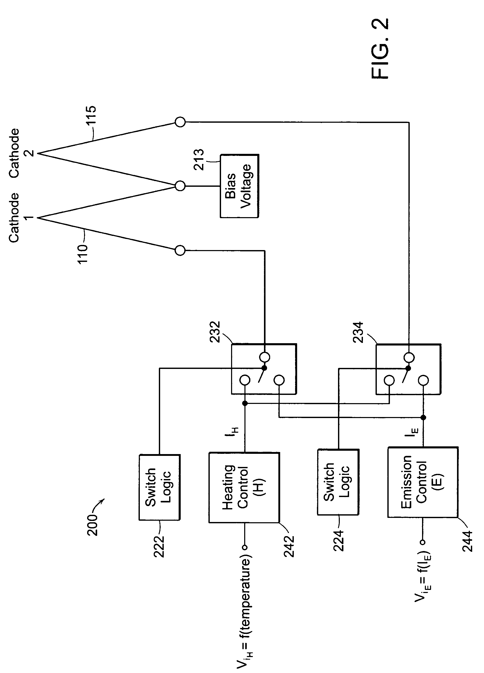
[0024]An ionization gauge controller (not shown) may heat one cathode 110 (e.g., an...


PUM

PropertyMeasurementUnit
temperatureaaaaaaaaaa

Abstract

A method and apparatus for operating a multi-hot-cathode ionization gauge is provided to increase the operational lifetime of the ionization gauge in gaseous process environments. In example embodiments, the life of a spare cathode is extended by heating the spare cathode to a temperature that is insufficient to emit electrons but that is sufficient to decrease the amount of material that deposits on its surface or is optimized to decrease the chemical interaction between a process gas and a material of the at least one spare cathode. The spare cathode may be constantly or periodically heated. In other embodiments, after a process pressure passes a given pressure threshold, plural cathodes may be heated to a non-emitting temperature, plural cathodes may be heated to a lower emitting temperature, or an emitting cathode may be heated to a temperature that decreases the electron emission current.

Description

BACKGROUND OF THE INVENTION[0001]The most common hot-cathode ionization gauge is the Bayard-Alpert (B-A) gauge. The B-A gauge includes at least one heated cathode (or filament) that emits electrons toward an anode, such as a cylindrical wire grid, defining an anode volume (or ionization volume). At least one ion collector electrode is disposed within the ionization volume. The anode accelerates the electrons away from the cathode towards and through the anode. Eventually, the electrons are collected by the anode.[0002]In their travel, the energetic electrons impact gas molecules and atoms and create positive ions. The ions are then urged to the ion collector electrode by an electric field created in the anode volume by the anode, which may be maintained at a positive 180 volts, and an ion collector, which may be maintained at ground potential. A collector current is then generated in the ion collector as ionized atoms collect on the ion collector. The pressure of the gas within the ...

Claims


Application Information

Patent Timeline
Patent Type & Authority Patents(United States)
IPC IPC(8): G01N27/62G01L21/30
CPCH01J41/04
Inventor CARMICHAEL, LARRY K.BORENSTEIN, MICHAEL D.ARNOLD, PAUL C.BLOUCH, STEPHEN C.KNOTT, RICHARD A.
Owner MKS INSTR INC
Why Eureka
Try Eureka