
Guidance and control for an autonomous soaring UAV

a technology of autonomous soaring and guidance system, which is applied in the direction of gliders, navigation instruments, instruments, etc., can solve the problems that no known practical control and guidance system has been developed for uavs to take advantage of thermal benefits, and achieve the effect of increasing the range and endurance of uavs

Inactive Publication Date: 2008-10-07
NAT AERONAUTICS & SPACE ADMINISTATION UNITED STATES OF AMERICA AS REPRESENTED BY THE DIRECTOR OF THE +1
View PDF6 Cites 62 Cited by
  • Summary
  • Abstract
  • Description
  • Claims
  • Application Information

AI Technical Summary

Benefits of technology

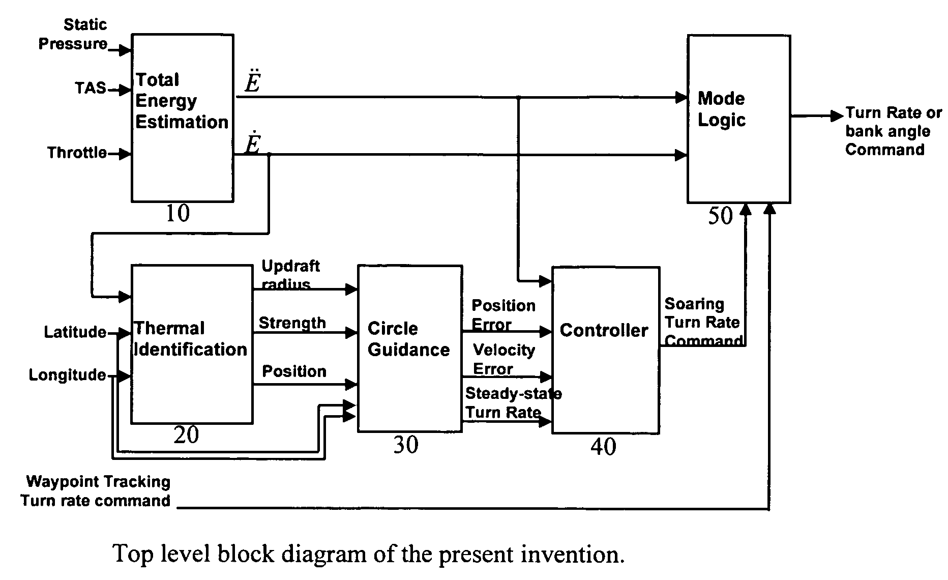
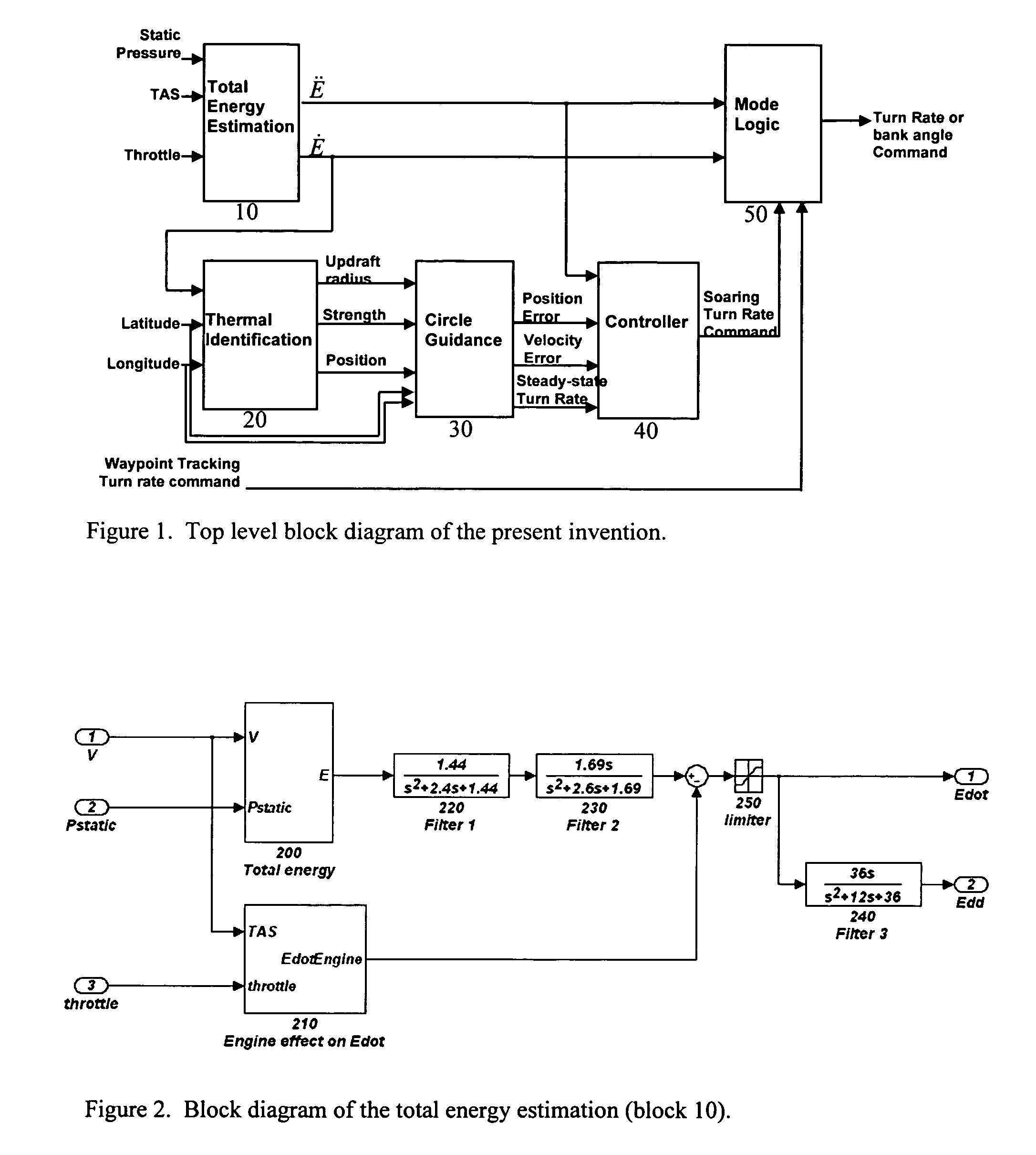
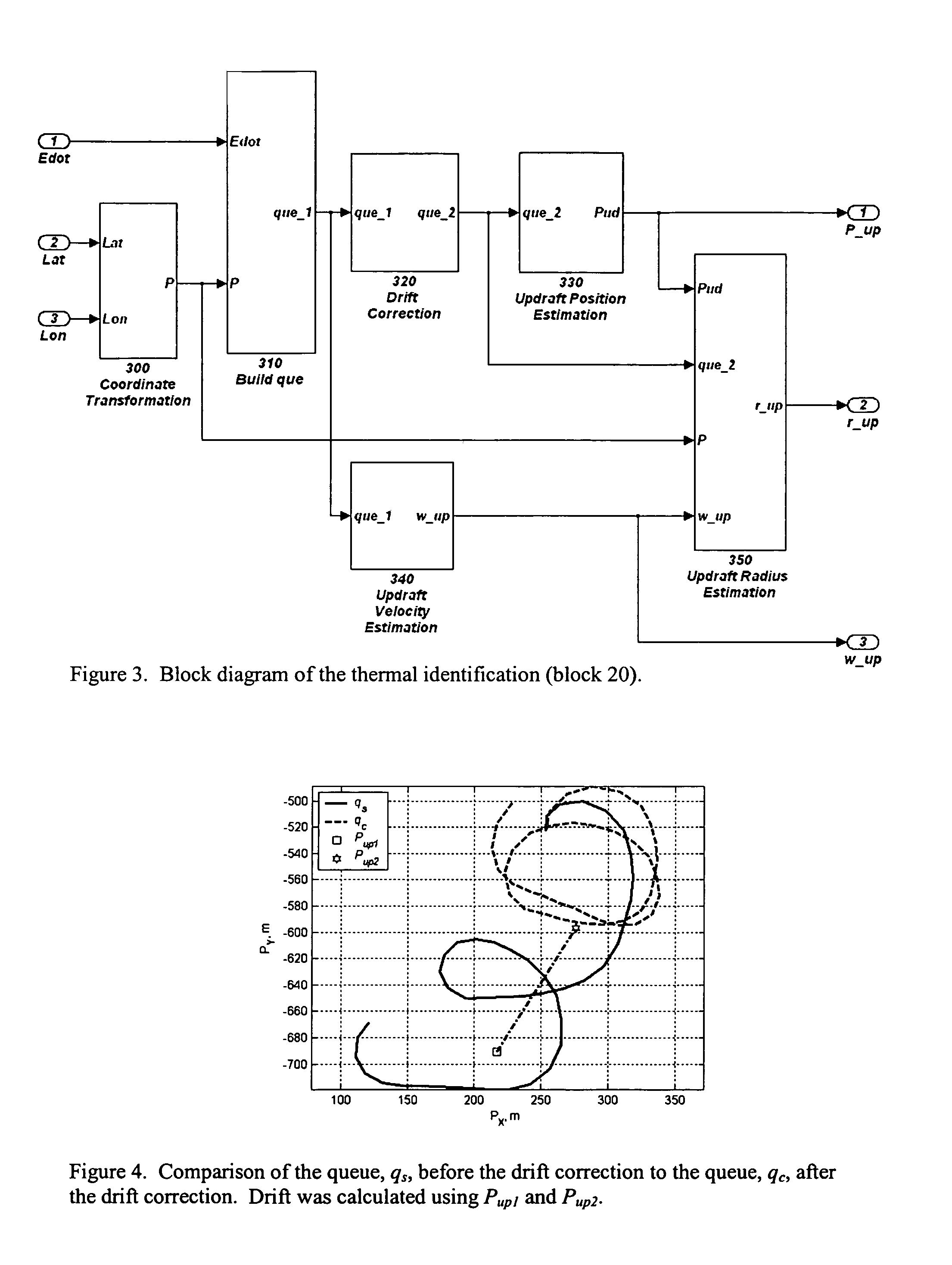
[0009]The invention proposed herein comprises a system and method of guidance and control for autonomous UAVs that allow the UAVs to locate and use thermals in order to increase the range and endurance of the UAVs.

Problems solved by technology

However, until the present invention, no known practical control and guidance system has been developed for UAVs to take advantage of the benefits of thermals.

Method used


Image

  • Guidance and control for an autonomous soaring UAV
  • Guidance and control for an autonomous soaring UAV
  • Guidance and control for an autonomous soaring UAV

Examples


Embodiment Construction

[0022]The following nomenclature will be employed herein to describe the present invention:[0023]a equatorial radius of the earth, m[0024]D estimated thermal drift velocity, m / s[0025]errp position error, m[0026]errsumsq sum squared error, m2 / s2 [0027]er{circumflex over (r)}sumsq sum squared error for perturbed thermal radius, m2 / s2 [0028]errv velocity error, m / s[0029]errw weighted error, m / s[0030]er{circumflex over (r)}w weighted error for perturbed thermal radius, m / s[0031]Ė energy rate, N·m[0032]Ėmotor total energy rate due to the motor, N·m / s[0033]Ë energy acceleration, m / s2 [0034]Ën normalized energy acceleration, m / s2 [0035]g gravitational constant, m / s2 [0036]H influence vector[0037]hest estimated aircraft altitude, m[0038]i queue index[0039]k current measurement index[0040]k1 energy acceleration gain, unitless[0041]k2 position error gain, unitless[0042]k3 velocity error gain, unitless[0043]L learning rate, 1 / s2 [0044]Lat latitude of aircraft, rad[0045]Lat0 latitude of X Y ref...


PUM


Abstract

The present invention provides a practical method for UAVs to take advantage of thermals in a manner similar to piloted aircrafts and soaring birds. In general, the invention is a method for a UAV to autonomously locate a thermal and be guided to the thermal to greatly improve range and endurance of the aircraft.

Description

STATEMENT OF GOVERNMENT INTEREST[0001]The invention described herein may be manufactured and used by or for the Government of the United States of America for governmental purposes without payment of any royalties thereon or therefor.BACKGROUND OF THE INVENTION[0002]1. Field of the Invention[0003]The present invention relates generally autonomous soaring for uninhabited air vehicles (UAVs), particularly to improved endurance for autonomous soaring UAVs, and more particularly to using thermals or convective thermals to improve the performance of UAVs.[0004]2. Description of the Related Art[0005]Glider pilots have been using buoyant plumes of air found in the lower atmosphere, normally referred to as thermals, in order to extend the distance that a glider may travel for many years.[0006]Several systems have been developed to assist pilots of gliders or low-powered aircraft to locate such thermals in order to provide improved range, endurance, or cross-country speed. For example, U.S. ...

Claims


Application Information

Patent Timeline
IPC IPC(8): G05D1/00B64C13/00B64C19/00B64C31/02G01C23/00
CPCG05D1/0005B64C2201/141B64U2201/10
Inventor ALLEN, MICHAEL J.
Owner NAT AERONAUTICS & SPACE ADMINISTATION UNITED STATES OF AMERICA AS REPRESENTED BY THE DIRECTOR OF THE
Learn More