Hand accessory usable with an implement handle

Inactive Publication Date: 2008-10-07
FROST JOHN H
View PDF13 Cites 20 Cited by
  • Summary
  • Abstract
  • Description
  • Claims
  • Application Information

AI Technical Summary

Benefits of technology

[0026]The greatest stress receiving are of bridge 440 is still primary contact point 406 which at the outer area of lever 408 has a more defined, flatter receiving area than embodiment 300. Fulcrum platform 402 of tough ball anchor 410 with ridge 404 pressing into and relocating the hand's lower tough ball 39 as repositioned fleshy ridge 14 (FIG. 32) is still probably the strongest supporting anchor for bridge 440, however ridge 404 has been re-angled, arcing against lower tough ball 39 in such a manner th

Problems solved by technology

Of great importance, the bridges connecting these contact points need to flex through a certain necessary range of hand movement during the swing, and this last requirement has been the most challenging because areas in the hand move in opposite directions to each other, and in the case of top hand grip of a bat, change directions during the gripping motion.
It became apparent however, that simply filling certain areas was not enough and that the structure, now more aptly described as a “bridge” or a “lever”, needs to work in conjunction with certain specific movements of the hand in order to leverage (rather than block by filling) the implement handle into a more powerful position.
Because the hands are not static during the swing, the hand accessory needs to be flexible, yet still hold the handle away from the bridged over sensitive areas, which has been the great difficulty in prior art devices.
While some high school players have used it satisfactorily in the playing of baseball, its performance previously was not up to pro standards.
The answer was originally thought to be simply that the hand is composed of so many sensitive areas (bones and tendons), that it was nearly impossible to contact the tough areas (muscle and fleshy areas) without affecting these sensitive areas, so the hand accessory would have to be very specific with many different angles, and no matter how much smoothing or reducing of material in the sensitive areas, it was not satisfactory unless the tough, adjacent areas nearby (sometimes within one-sixteenth of an inch) were contacted to hold the structure against the force of the recoili

Method used


Image

  • Hand accessory usable with an implement handle
  • Hand accessory usable with an implement handle
  • Hand accessory usable with an implement handle

Examples


embodiment 300

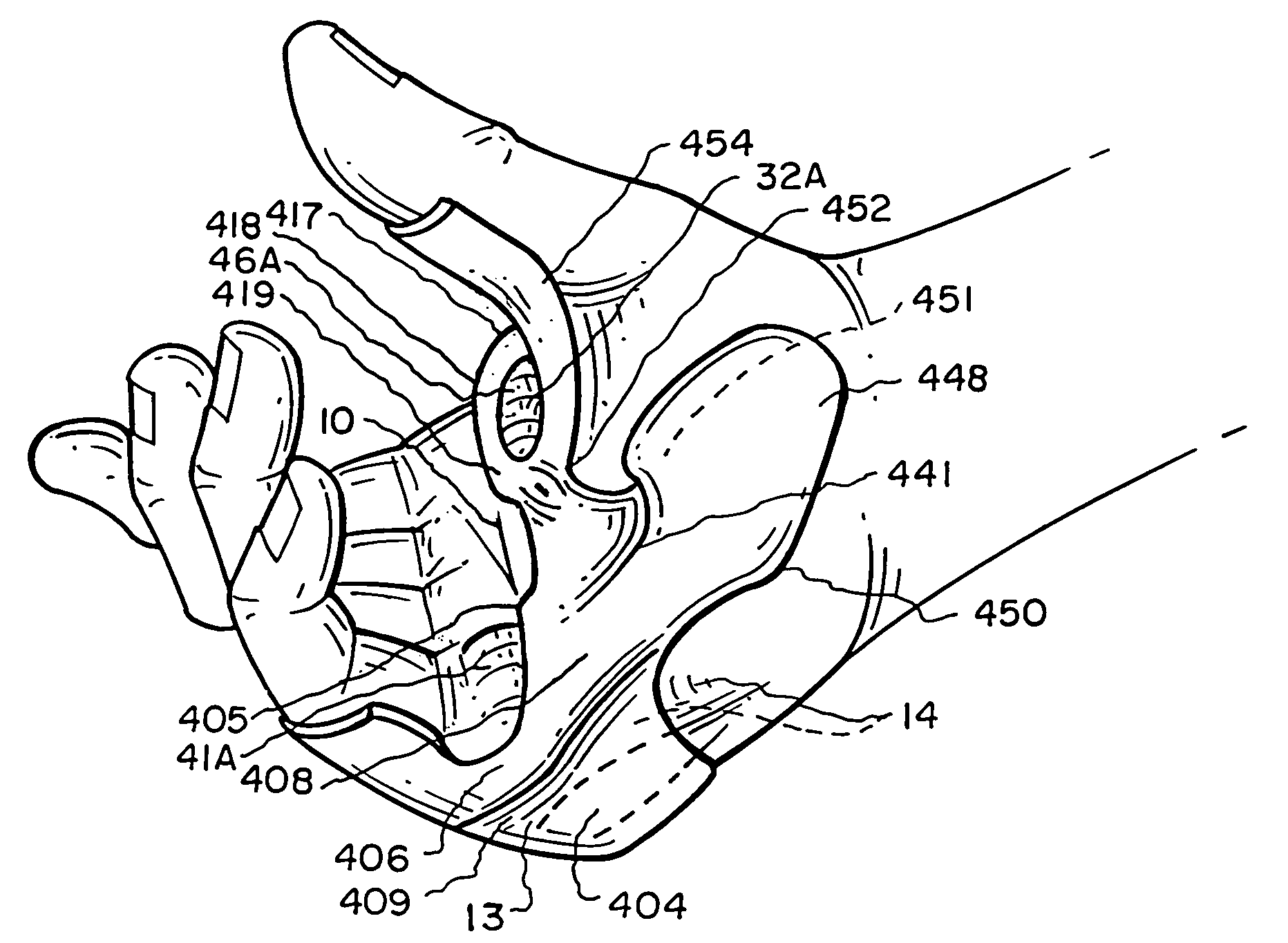
[0094]Much of the structure of lifeline anchor 320 is thumb base wedge 352, which contours the thumb 44 with thin material extending upwardly from swivel 330 and inwardly from lifeline contact 324, thumb base wedge 352 resting against the hand's thumb bases 30 and 31, and extending upwardly to circular thumb attachment 322, thence extending to the back side of the hand to glove / web anchor 326 pressing into the top of the hand's upper web 46 (from the back side of the hand) and serving to locate and fix the hand accessory to a glove. Glove / web anchor 326 is constructed at such an angle as to create forward tension at thumb attachment 322 away from the hand's sensitive thumb bones 34 when glove / web anchor 326 is flexed slightly forward to its attachment area of a glove. Glove / web anchor 326 also may receive contact from recoiling handle 48 depending on the user's grip, but the great majority of energy is dissipated in the lower hand through structure in the lower areas of embodiment 3...

embodiment 203

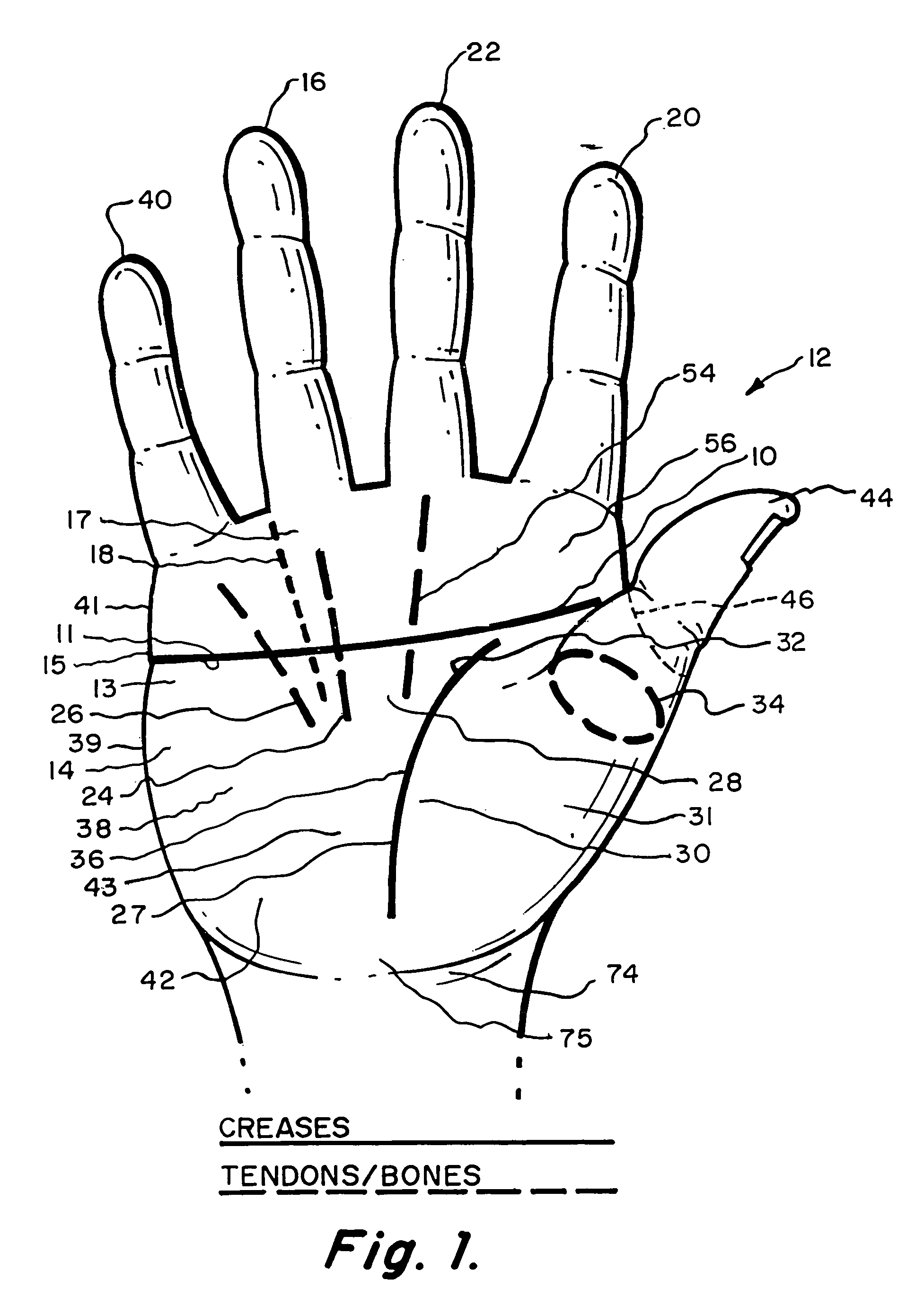
[0100]The location and composition of lever 308 is critical to the success of direct contact stress absorption. If the pathway of lever 308 towards thumb base / wrist anchor 350 moves upwardly (as in embodiment 203) angling over tough ball 38 with too much thickness, even though a tough area, discomfort from direct pressure of handle 48 will occur. The pathway of lever 308 must be as low as possible while still reaching its junction with thumb base / wrist anchor 350 (also at the lowest point allowed by stress receiving area wrist hollow 75), such that lever 308 runs primarily along the bottom of tough ball 38 (not supported by tough ball 38) but supported by fulcrum platform 302 anchored at lower tough ball 39 and “locked” into fleshy relocation channel 309, actually serving to “widen” the hand. Refinement of portions of lever 308 make hand accessory 300 workable with all types of bottom hand gripping of a baseball bat and are further explained in a final paragraph on “bottom hand grip...

embodiment 400

[0108]Without hand accessory 400, handle 48 recoiling or resting in the upper hand will push web area 32 to 46 downwardly / inwardly toward index knuckle 56 exposing thumb joint 34 to injury from handle 48. A major feature of embodiment 400 is a relocated lower web 32A whereby lower web 32 is pressed inwardly / upwardly spacing handle 48 away from thumb joint 34. A skin relocation originates at web point 426 and moves in two directions, the skin moving with mid-palm anchor 415 downwardly when gripping, the skin being displaced by mid-palm anchor 415 upwardly, that is, pressure from the gripping hand at lifeline / web anchor 425 pushes mid-palm anchor 415 pressed as one with the hand's thin palm skin downwardly moving into the tough ball area adding bulk to tough ball areas 38 and 39 increasing support of bridge 440, more importantly, the anchoring depth of lifeline / web anchor 425 displaces fleshy lower web 32 upwardly toward thumb joint 34 partially overlapping and protecting the thumb jo...


PUM


Abstract

A hand accessory contoured to anchor into tough areas of a hand and bridge over sensitive areas in securing a grip on an implement handle, maximizing the transmission of force to the implement handle, minimizing stress received in the sensitive areas of the hand (primarily the upper areas) and increasing power transmission through tougher and stronger areas of the hand (primarily the lower areas).

Description

REFERENCE TO PRIOR APPLICATION[0001]This application is a continuation-in-part of U.S. patent application Ser. No. 11 / 115,805, now U.S. Pat. No. 7,179,180 filed Apr. 26, 2005, by the present inventor.BACKGROUND OF THE INVENTION[0002]1. Field of the Invention[0003]The field of this invention relates generally to hand accessories useful for improving power transmission and improving the gripping movement of the hands of a human in connection with the handle of an implement, such as a baseball bat, thereby transmitting a greater amount of power and control of flight to a baseball that is struck with the baseball bat.[0004]2. Description of the Related Art[0005]The subject matter of the present invention is an improvement over the structure defined within CIP patent application Ser. No. 11 / 115,805, filed Apr. 26, 2005, entitled HAND ACCESSORY USABLE WITH AN IMPLEMENT HANDLE, U.S. Pat. No. 5,180,165, issued Jan. 19, 1993, entitled HAND ACCESSORY, and U.S. Pat. No. 5,588,651, issued Dec. ...

Claims


Application Information

Patent Timeline
IPC IPC(8): A63B69/00
CPCA63B59/0014A63B69/0002A63B21/1434A63B2069/0008A63B21/4017A63B60/06A63B60/08A63B60/10
Inventor FROST, JOHN H.
Owner FROST JOHN H
Why Eureka
Try Eureka