Electrochemical fuel deoxygenation system

a fuel deoxygenation and electrochemical technology, applied in the direction of electric/magnetic refining, chemical/physical/physicochemical processes, crystal growth processes, etc., can solve the problems of inhibiting combustion, affecting the fuel line, and dissolved oxygen in hydrocarbon jet fuels, etc., to reduce coking, reduce coking, and reduce the effect of dissolved oxygen

Active Publication Date: 2008-10-07
RTX CORP
View PDF16 Cites 32 Cited by
  • Summary
  • Abstract
  • Description
  • Claims
  • Application Information

AI Technical Summary

Benefits of technology

[0008]The present invention eliminates conventional oxygen permeable membranes as the electrode directly contacts the fuel. The present invention also eliminates the need for a absolute pressure differences, oxygen permeable membranes, and components with moving parts such as pumps.
[0009]The present invention therefore provides a method and system for the deoxygenation of hydrocarbon fuel to minimize coking in an inexpensive, size and weight efficient system.

Problems solved by technology

The presence of dissolved oxygen in hydrocarbon jet fuels may be objectionable because it supports oxidation reactions that yield undesirable by-products.
When aerated fuel is heated between 350° F. and 850° F. the oxygen initiates free radical reactions of the fuel resulting in deposits commonly referred to as “coke” or “coking.” Coke may be detrimental to the fuel lines and may inhibit combustion.
The formation of such deposits may impair the normal functioning of a fuel delivery system, either with respect to an intended heat exchange function or the efficient injection of fuel.
As the vacuum also introduces mechanical forces on the membrane, the membrane is supported on a porous stainless steel plate, which is relatively expensive and may be a diffusion barrier requiring a relative increase in the unit size.
Mechanical pumps and vacuum housings are also required which further increases the size and weight of the system.

Method used


Image

  • Electrochemical fuel deoxygenation system
  • Electrochemical fuel deoxygenation system
  • Electrochemical fuel deoxygenation system

Examples


Embodiment Construction

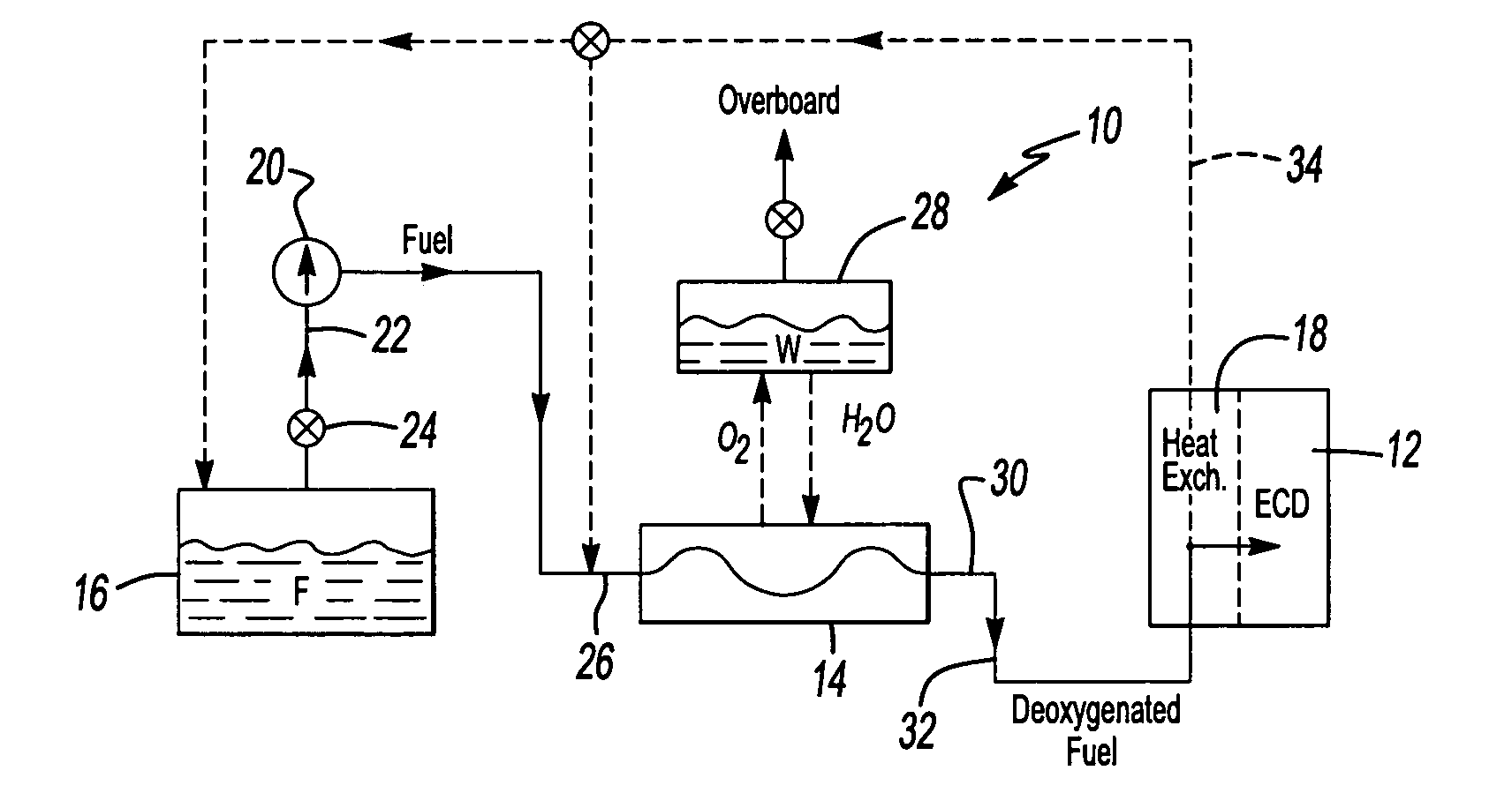
[0017]FIG. 1 illustrates a general perspective view of a fuel system 10 for an energy conversion device (ECD) 12. A deoxygenator system 14 receives liquid fuel F from a reservoir 16. The fuel F is typically a hydrocarbon such as jet fuel. The ECD 12 may exist in a variety of forms in which the fuel, at some point prior to eventual use for processing, for combustion or for some form of energy release, acquires sufficient heat to support autoxidation reactions and coking if dissolved oxygen is present to any significant extent in the fuel.

[0018]One form of the ECD 12 is a gas turbine engine, and particularly such engines in high performance aircraft. Typically, the fuel also serves as a coolant for one or more sub-systems in the aircraft, and in any event becomes heated as it is delivered to fuel injectors immediately prior to combustion.

[0019]A heat exchange section 18 represents a system through which the fuel passes in a heat exchange relationship. It should be understood that the ...


PUM

PropertyMeasurementUnit
surface textureaaaaaaaaaa
contact areaaaaaaaaaaa
poweraaaaaaaaaa

Abstract

A fuel system for an energy conversion device includes a deoxygenator system with an electrochemical conversion system to remove oxygen from fuel through conversion of the oxygen to water. The electrochemical conversion system is located within a fuel flow. On the fuel side ½O2+2H++2e−=>H2O while on the reverse side the opposite reaction occurs. From the electrochemical conversion system the water is then collected and / or expelled from the system.

Description

BACKGROUND OF THE INVENTION[0001]The present invention relates to the removal of dissolved oxygen from fuels, and more particularly to electrochemically converting the oxygen to water.[0002]The presence of dissolved oxygen in hydrocarbon jet fuels may be objectionable because it supports oxidation reactions that yield undesirable by-products. Jet fuel is often utilized in aircraft as a coolant for various systems in the aircraft. Dissolution of air in jet fuel results in an approximately 70 ppm oxygen concentration. When aerated fuel is heated between 350° F. and 850° F. the oxygen initiates free radical reactions of the fuel resulting in deposits commonly referred to as “coke” or “coking.” Coke may be detrimental to the fuel lines and may inhibit combustion. The formation of such deposits may impair the normal functioning of a fuel delivery system, either with respect to an intended heat exchange function or the efficient injection of fuel.[0003]Typically, lowering the oxygen conce...

Claims


Application Information

Patent Timeline
Patent Type & Authority Patents(United States)
IPC IPC(8): C25F7/00B01J19/00F23K5/08B01J19/08C10G32/00C10G32/02C10L1/00C25B1/02H01M4/70H01M8/06H01M8/10
CPCC10G32/02H01M8/0662H01M2008/1095Y02E60/522Y02E60/50B01D19/00C02F1/46
Inventor CIPOLLINI, NED EMIDIO
Owner RTX CORP
Why Eureka
Try Eureka