Noise filter and mounted structure of noise filter

a technology of noise filter and mounted structure, which is applied in the direction of fixed capacitor details, waveguides, feed-through capacitors, etc., can solve the problem that the noise removal effect of the three-terminal capacitor is not satisfactory, and achieve the effect of noise removal

Active Publication Date: 2008-10-07
TDK CORPARATION
View PDF4 Cites 14 Cited by
  • Summary
  • Abstract
  • Description
  • Claims
  • Application Information

AI Technical Summary

Benefits of technology

[0006]An object of the present invention is to provide a noise filter capable of further improving the noise removal effect, and a mounted structure of a noise filter.
[0021]The present invention successfully provides the noise filter capable of further improving the noise removal effect, and the mounted structure of the noise filter.

Problems solved by technology

However, the noise removal effect is not satisfactory yet with the three-terminal capacitor and the feedthrough capacitor (e.g., the multilayer feedthrough capacitor described in the foregoing Laid-Open No. 55-43869).

Method used


Image

  • Noise filter and mounted structure of noise filter
  • Noise filter and mounted structure of noise filter
  • Noise filter and mounted structure of noise filter

Examples


Embodiment Construction

[0048]The preferred embodiments of the present invention will be described below in detail with reference to the accompanying drawings. In the description, identical elements or elements with identical functionality will be denoted by the same reference symbols, without redundant description.

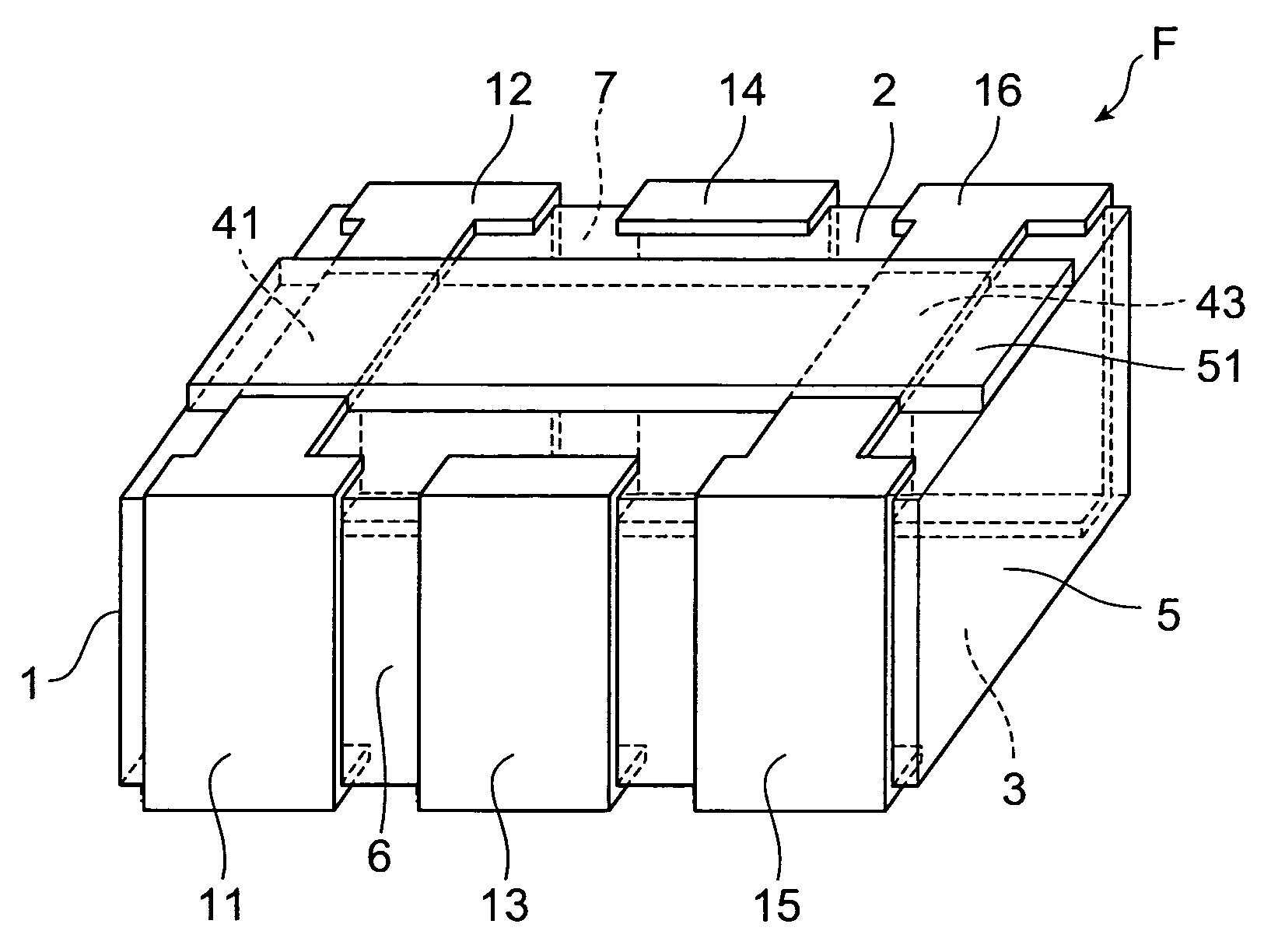
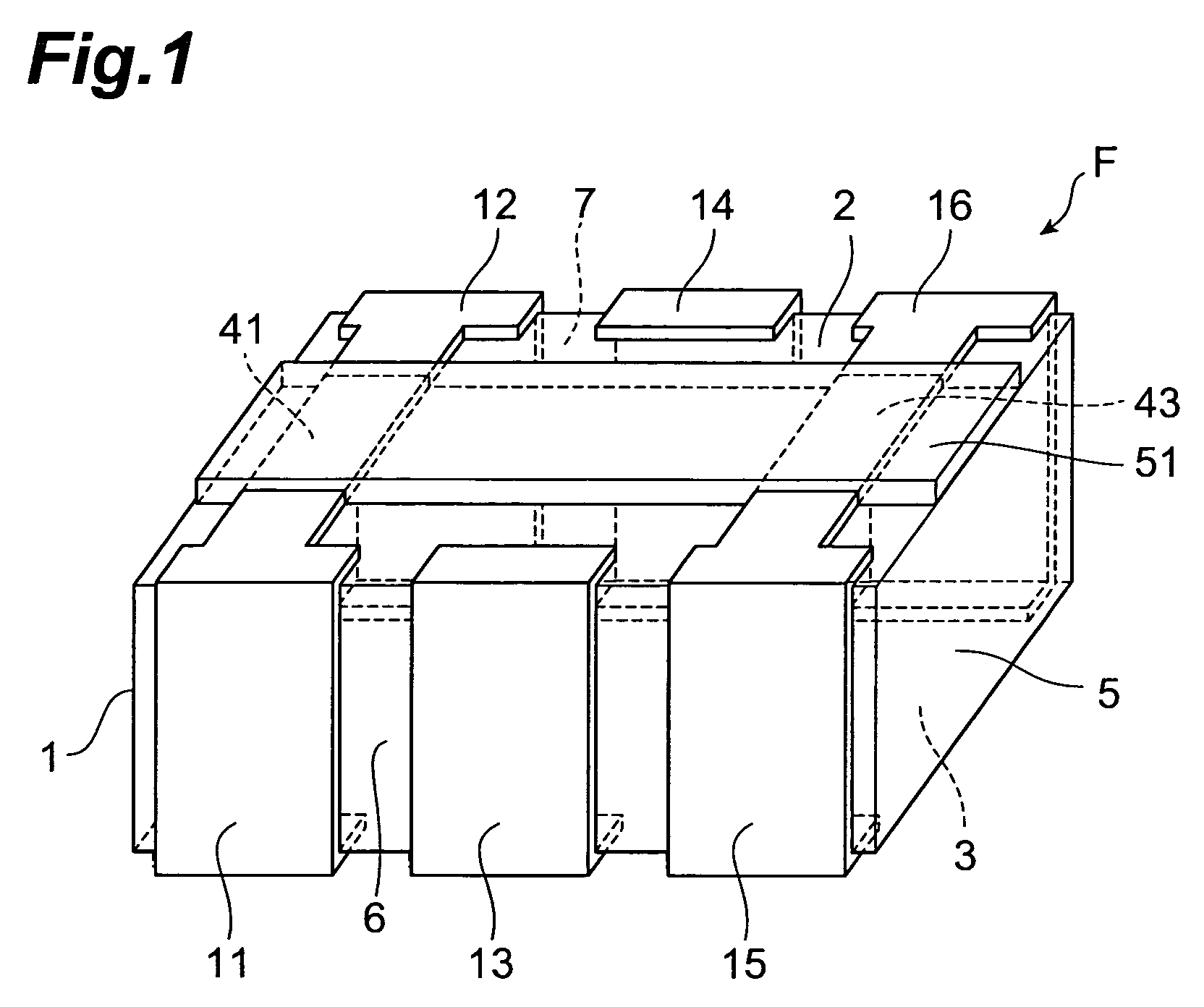
[0049]A configuration of a noise filter F according to an embodiment of the present invention will be described with reference to FIGS. 1 to 3. FIG. 1 is a perspective view of the noise filter according to the present embodiment. FIG. 2 is an exploded perspective view of an element body included in the noise filter according to the present embodiment. FIG. 3 is a schematic view for explaining a sectional configuration of the noise filter according to the present embodiment.

[0050]The noise filter F, as shown in FIG. 1, has an element body 1 of an approximately rectangular parallelepiped shape, and first to sixth terminal electrodes 11-16 disposed on the exterior of the element body 1. The element...


PUM

PropertyMeasurementUnit
widthaaaaaaaaaa
noise removalaaaaaaaaaa
noise removal effectaaaaaaaaaa

Abstract

A noise filter has an element body, first to fourth terminal electrodes, and a connection conductor. The first to fourth terminal electrodes are disposed on the exterior of the element body. The connection conductor is also disposed on the exterior of the element body. A capacitor is formed in the element body and is electrically connected between the first and second terminal electrodes and the third and fourth terminal electrodes. The first and second terminal electrodes are electrically connected through the connection conductor. The connection conductor is covered by a resin containing ferrite. Since the connection conductor is covered by the resin containing ferrite, the connection conductor and the ferrite-containing resin function as a ferrite bead inductor.

Description

BACKGROUND OF THE INVENTION[0001]1. Field of the Invention[0002]The present invention relates to a noise filter and a mounted structure of a noise filter.[0003]2. Related Background Art[0004]A three-terminal capacitor, a feedthrough capacitor, or the like is sometimes used as a noise filter for preventing leakage or penetration of noise through interconnections for power, signals, and so on. A known feedthrough capacitor is a multilayer feedthrough capacitor in which a signal-side internal electrode and a ground-side internal electrode are laminated through an insulator layer (e.g., reference is made to Japanese Patent Application Laid-Open No. 55-43869).SUMMARY OF THE INVENTION[0005]However, the noise removal effect is not satisfactory yet with the three-terminal capacitor and the feedthrough capacitor (e.g., the multilayer feedthrough capacitor described in the foregoing Laid-Open No. 55-43869).[0006]An object of the present invention is to provide a noise filter capable of furthe...

Claims


Application Information

Patent Timeline
Patent Type & Authority Patents(United States)
IPC IPC(8): H03H7/00
CPCH01G4/232H01G4/30H01G4/35Y10T29/49016Y10T29/435H03H9/46
Inventor TOGASHI, MASAAKI
Owner TDK CORPARATION
Why Eureka
Try Eureka