Dynamic carousel robotic workcell

a robotic workcell and dynamic technology, applied in the field of robotic workstations, can solve the problems of shielding, consuming some of the work space of the robot, and affecting the work of the end-effector, and achieve the effect of reducing travel

Active Publication Date: 2008-10-14
ARIES INNOVATIONS
View PDF4 Cites 22 Cited by
  • Summary
  • Abstract
  • Description
  • Claims
  • Application Information

AI Technical Summary

Benefits of technology

[0014]The present invention, roughly described, pertains to a dynamic workcell. The dynamic workcell includes a three dimensional positioning robot positioned adjacent a plurality of operation stations. A plurality of movable part fixtures located adjacent to the robot is also provided. A fixture location controller directing positioning of the part fixtures relative to the plurality of operation stations to minimize travel between an operation station and a part fixture is provided.
[0015]In a further aspect, the invention is a method for operating a workcell including a three dimensional positioning robot and a plurality of movable part fixtures. The method may include the steps of: mapping ones of a plurality of testers to the plurality of movable part fixtures; maintaining the position of each movable part fixture; determining a current location of an active part fixture relative to a mapped tester; and minimizing the distance between the mapped tester and the active part fixture.

Problems solved by technology

This air-space requirement can cause problems when machines are packed tightly together in a workcell, as the robot may have to retreat to a safe location a short distance from the machine to perform the rotation, then go back to bring the new part to the machine.
The only drawback to this end-effector, as compared to the dual end type, is that even when both paddles are pitched down, the distance is longer than the old end-effector.
These obstacles may be safety enclosures, tester components or the robot itself.
This shield unfortunately consumes some of the robot's work space and interferes with the end-effector when the robot is exchanging disks on an adjacent tester.
Because robots and test stations are quite expensive, performance improvements to new and existing robot installations are crucial.

Method used


Image

  • Dynamic carousel robotic workcell
  • Dynamic carousel robotic workcell
  • Dynamic carousel robotic workcell

Examples


Embodiment Construction

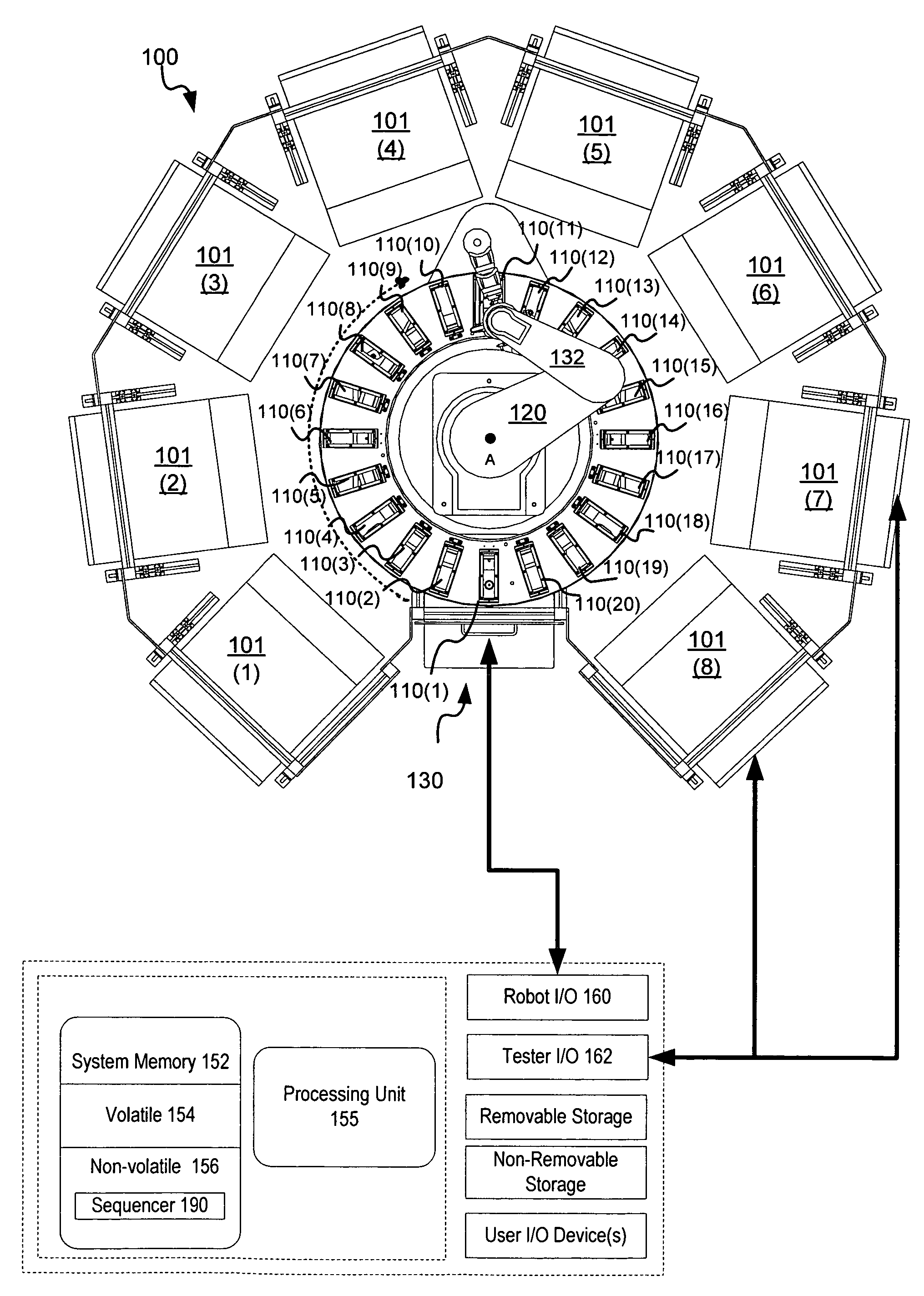
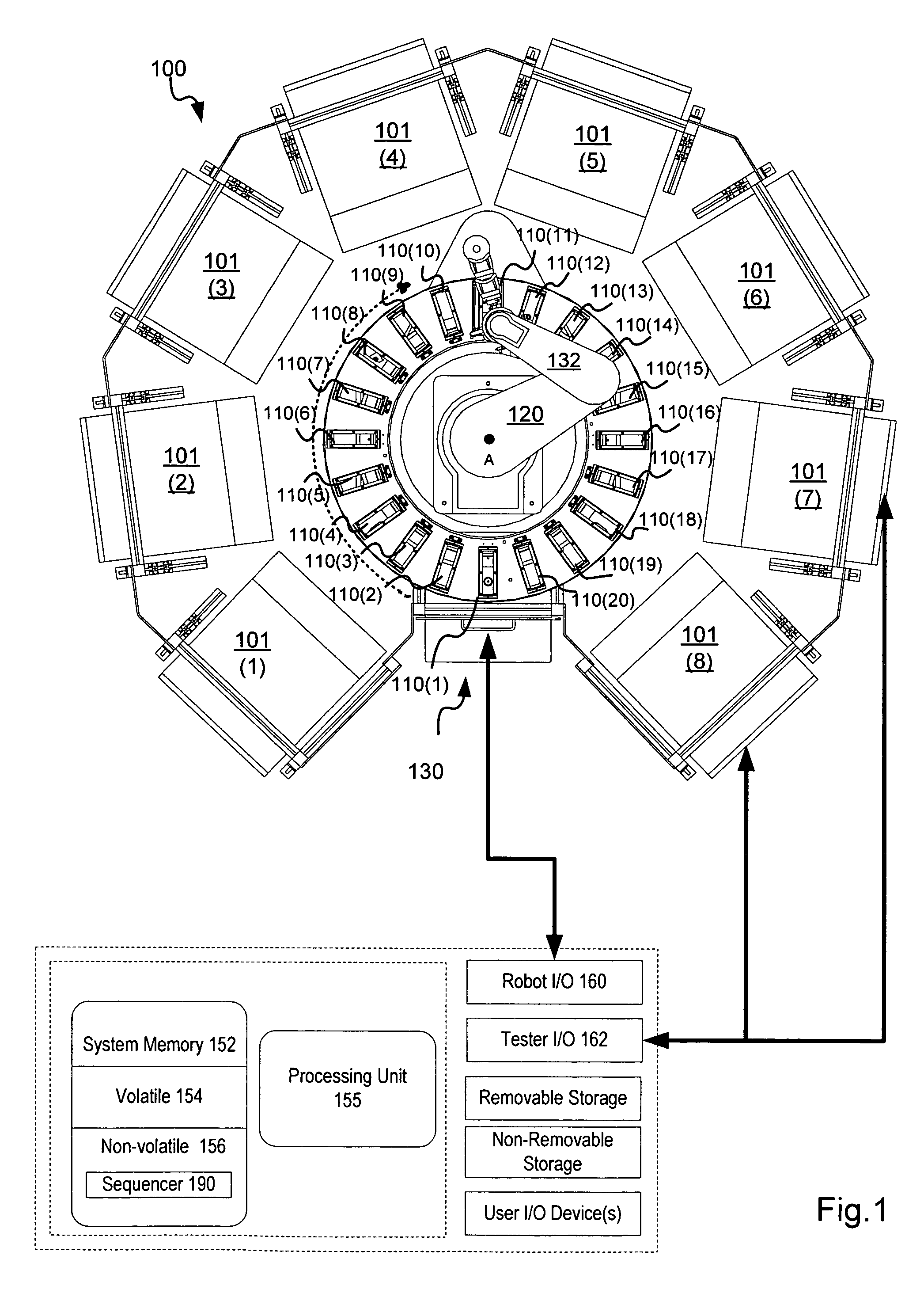
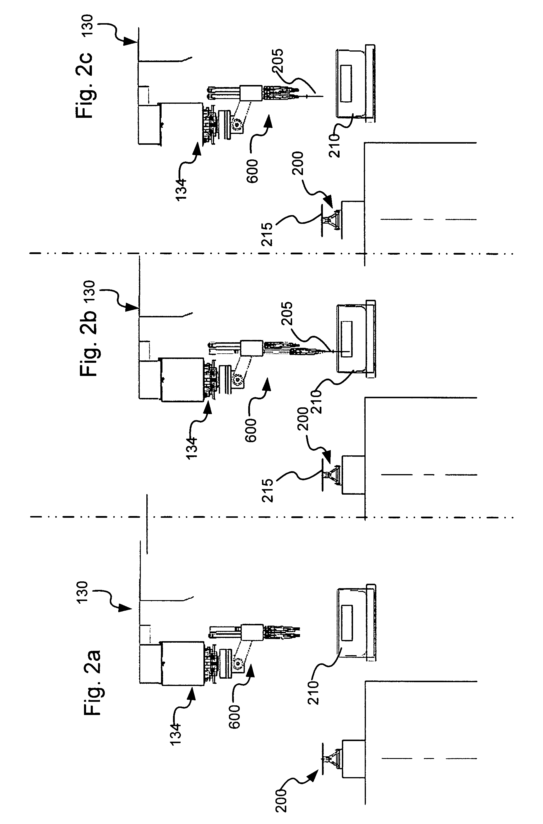
[0028]In one embodiment, the invention provides an improved robotic workcell using a dynamic carousel and an improved end effector. A dynamic carousel assisted workcell 100 uses a dynamic carousel 130 to rotationally position parts relative to the testing robot, reducing the distance between the robot arm's current position and its destination. This eliminates the need for the robot to continuously travel to a fixed location and provides a dramatic reduction in the distance traveled and cycle times, and an increase in output. In addition, the carousel assisted workcell uses a parallel end-effector that requires no rotation and can exchange disks at or below 1.0 seconds. The improved end-effector requires very little air-space and exchanges are not affected by how tightly packed the machines are in the workcell.

[0029]The carousel assisted workcell has applications in many fields, including medical, semiconductor, rigid media and / or food processing. In this specification, the workcell...


PUM


Abstract

A dynamic workcell includes a three dimensional positioning robot positioned adjacent a plurality of operation stations. A plurality of movable part fixtures located adjacent to the robot is also provided. A fixture location controller directing positioning of the part fixtures relative to the plurality of operation stations to minimize travel between an operation station and a part fixture is provided. A method for operating a workcell may include the steps of: mapping ones of a plurality of testers to the plurality of movable part fixtures; maintaining the position of each movable part fixture; determining a current location of an active part fixture relative to a mapped tester; and minimizing the distance between the mapped tester and the active part fixture.

Description

BACKGROUND OF THE INVENTION[0001]1. Field of the Invention[0002]The present invention is directed to a robotic workstation such as those useful in wafer processing.[0003]2. Description of the Related Art[0004]Robotic workstations are applied to numerous industries. In the data storage industry, they have been applied to magnetic disk testing, inspecting and processing. In the storage industry, robotic workstations are centered around a robotic arm operated by a programmable controller which moves disks from a fixture to testing stations placed proximate to the robotic arm. Typically, input disks are provided to a workstation by a human operator in a cassette or carrier and additional empty carriers are used for output disks, finished after the result of testing operations.[0005]In conventional robot-based pick-and-place workcells, input and output is stowed in a specific static location. The robot travels to this location to pick parts and brings them to other machines, processors a...

Claims


Application Information

Patent Timeline
Patent Type & Authority Patents(United States)
IPC IPC(8): B65H1/00
CPCB25J9/0096B25J15/0052G11B17/26H01L21/67742
Inventor KIAIE, JUBINDADIOMOV, ALEX
Owner ARIES INNOVATIONS
Why Eureka
Try Eureka