
Molded product and process for manufacturing the same

a technology of molded products and manufacturing processes, applied in the direction of casings/cabinets/drawers, casings/cabinets/drawers details, electrical appliances, etc., can solve the problems of increased manufacturing cost, large amount of manufacturing man-hour requirements, and further degradation of decorative surface 207, etc., to achieve fine decorativeness and reduce manufacturing steps

Inactive Publication Date: 2008-10-14
TOYODA GOSEI CO LTD
View PDF11 Cites 2 Cited by
  • Summary
  • Abstract
  • Description
  • Claims
  • Application Information

AI Technical Summary

Benefits of technology

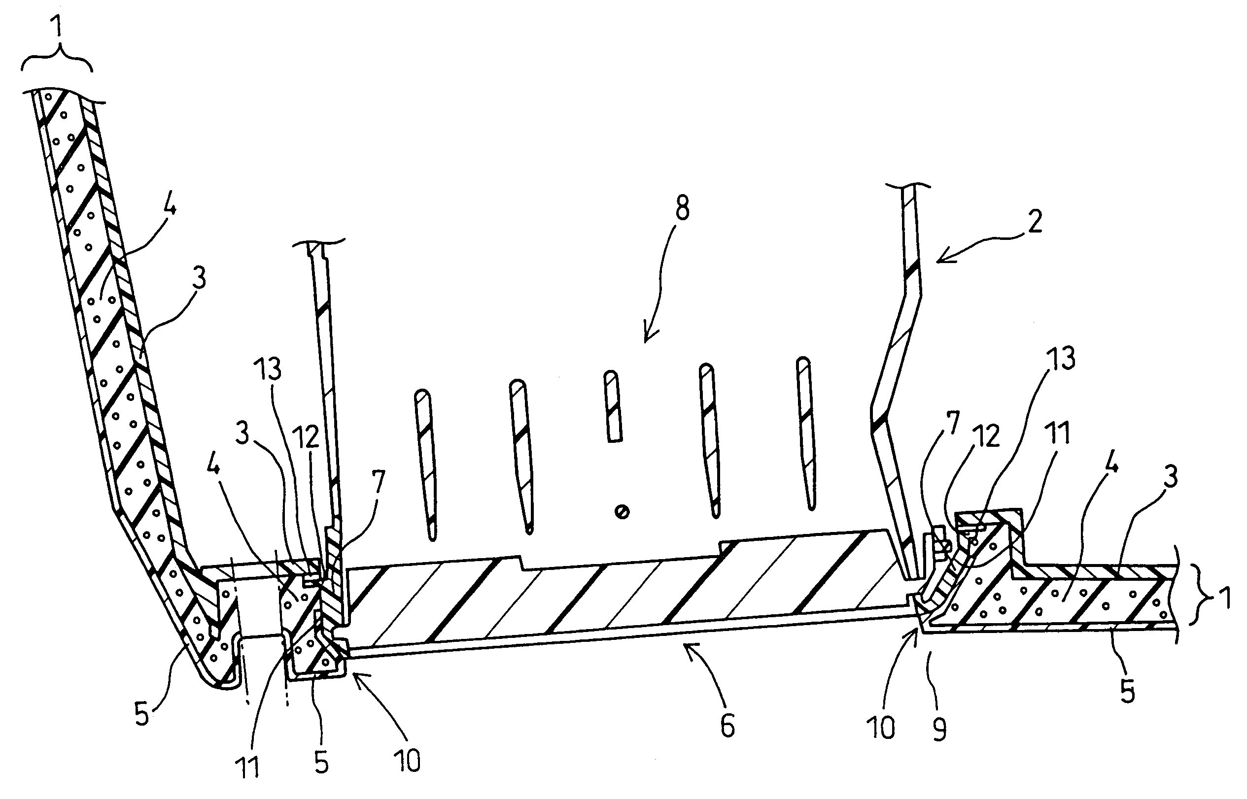
[0011]The present invention has been developed in view of the aforementioned circumstances. It is therefore an object of the present invention to provide a molded product which makes it possible to form a decorative surface offering fine decorativeness with a lesser number of manufacturing steps, and a process for manufacturing the same.
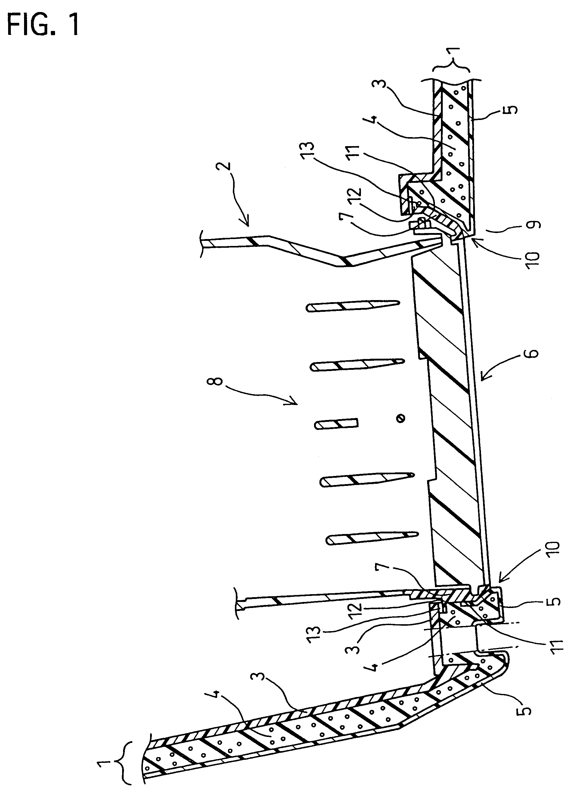
[0041]In the molded product according to the first aspect of the present invention, the opening end is fastened integrally to the skin at least at a part thereof. Accordingly, it is possible to inhibit the foamed layer from being exposed in the decorative surface or to inhibit the foamed layer from being visible. Moreover, no covering component part such as a bezel is required independently to cover the frame of the window. Consequently, no step or gap resulting from the covering component part occurs between the molded subassembly and the opening end. In addition, when the end surface of the opening end is fastened integrally to the skin, the end surface is covered with a part of the molded subassembly, and is covered with the skin as well. Accordingly, the molded subassembly and the opening end have decorative continuity, or the decorative surface is free from the step or gap occurring between the molded subassembly and the opening end. Further, no step or gap occurs between the opening end and the skin. Consequently, no foamed resin leaks between the opening end and the skin. Furthermore, the opening end is held directly or indirectly by the substrate of the molded subassembly. Moreover, no covering component part is needed which is molded independently in advance. As a result, it is possible to reduce the weight of molded products.
[0042]In the molded product according to the second aspect of the present invention, the decorative component part gives decorations which were different from those given by the molded subassembly. Accordingly, it is possible to further improve molded products in terms of the decorativeness. Moreover, the parting line between the decorative component part the skin is visible as being joined closely or substantially seamless in the decorative surface. Consequently, the decorative component part and the skin are made more continuous in view of the decorativeness.
[0043]In the manufacturing process according to the third aspect of the present invention, it is possible to integrate the skin with the opening end of the functional component part in a single step. Accordingly, it is possible to manufacture molded products which offer good integrity, with ease.
[0044]In the manufacturing process according to the fourth aspect of the present invention, the decorative component part and the skin layer are pressed to close with each other at the parting line between them by a foaming pressure exerted by the foaming raw material. Accordingly, it is possible to form a parting line, which is visible as being joined closely or substantially seamless in the decorative surface, with ease. Note that it is possible form such a parting line by the positioning plate which is disposed on one of the opposite molding surfaces of the mold. In this instance, it is possible to position the decorative component part on one of the opposite molding surfaces by the positioning plate easily and reliably. Moreover, when the length and shape of the positioning plate are designed appropriately, it is possible as well to mask the window-forming surface in one of the opposite molding surfaces of the mold, for example.

Problems solved by technology

Thus, the decorativeness of the decorative surface 207 might be further degraded.
In addition, the completed product might have a problem with the increased manufacturing cost, because the manufacturing process in which the bezel 203 molded independently is assembled with the molded subassembly 204 requires a great deal of manufacturing man-hour requirements.
Accordingly, gaps might occur between the skin and the substrate when the skin contracts, or the foamed resin might leak between them, because the opening end of the skin is not bonded to the opening end of the substrate.
Moreover, the appearance of the molded product might be degraded, because the functional component part is disposed in and fixed to the window so that gaps occur between the frame of the window and the functional component part.
In addition, the molded product has a problem with a great deal of manufacturing man-hour requirements still, because a cutting step is needed in which the skin is cut to form the window.

Method used


Image

  • Molded product and process for manufacturing the same
  • Molded product and process for manufacturing the same
  • Molded product and process for manufacturing the same

Examples


examples

[0097]The present invention will be hereinafter described in more detail with reference to specific preferred embodiments illustrated in the accompanying drawings. In Example Nos. 1 through 5, molded products according to the present invention will be described. In Example Nos. 6 and 7, processes according to the present invention for manufacturing the molded products will be described.

example no.1

Example No. 1

[0098]In a molded product provided integrally with a function component part according to Example No. 1 of the present invention, an automotive instrument panel makes a molded subassembly, and a register makes a functional component part. FIG. 1 is a schematic cross-sectional view for illustrating the present molded product according to Example No. 1. Note that Example No. 1 relates to the first aspect of the present invention.

[0099]As illustrated in FIG. 1, the present molded product according to Example No. 1 comprises a molded subassembly 1, and a functional component part 2. The molded subassembly 1 includes a substrate 3, a foamed layer 4 formed on the substrate 3, and a skin 5 covering the foamed layer 4. Moreover, a window 6 (i.e., a through hole) is formed in the molded subassembly 1.

[0100]The functional component part 2 includes an opening end 7, and a functional unit 8. The opening end 7 forms the frame of the window 6. The functional unit 8 is disposed in the...

example no.2

Example No. 2

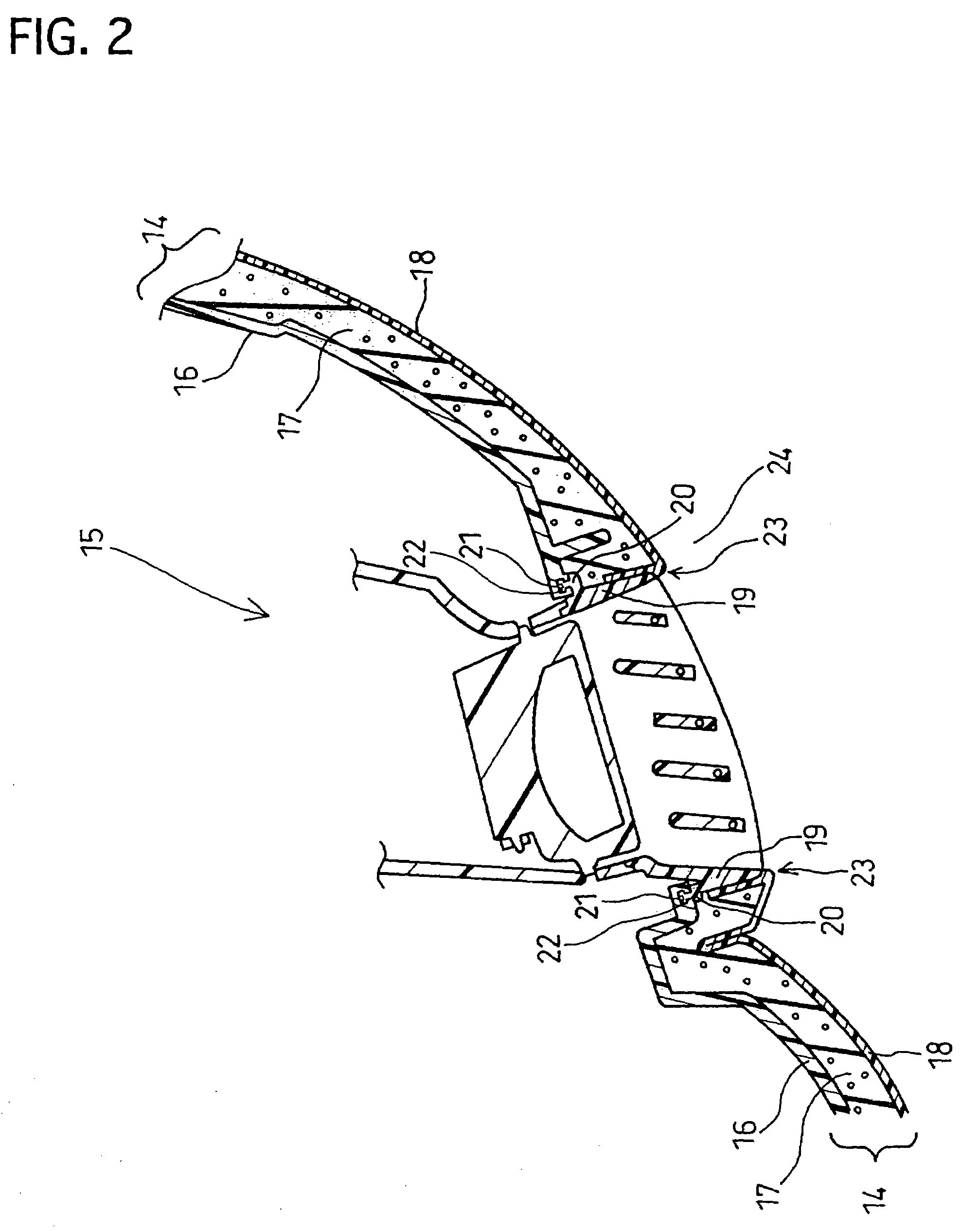
[0102]In a molded product according to Example No. 2 of the present invention, an automotive instrument panel makes a molded subassembly, and a side register makes a functional component part. Note that Example No. 2 relates to the first aspect of the present invention. Except that the functional component part is different from that of Example No. 1 and the opening end is held to the substrate 3 by engagement, the present molded product according to Example No. 2 has the same arrangements as those of Example No. 1. FIG. 2 is a schematic cross-sectional view for illustrating the present molded product according to Example No. 2.

[0103]Similarly to Example No. 1, the present molded product according to Example No. 2 comprises a molded subassembly 14, and a functional component part 15. The molded subassembly 14 includes a substrate 16, a foamed layer 17, and a skin 18. The substrate 16 is provided with engagement holes 21 which face a holder end 20 of an opening end 19 in...


PUM

PropertyMeasurementUnit
thicknessaaaaaaaaaa
heightaaaaaaaaaa
thicknessaaaaaaaaaa

Abstract

In a molded product, at least an opening end, forming a window frame of a window formed as a part of a molded subassembly, is fastened integrally to a skin of the molded subassembly. Alternatively, a decorative component part is disposed on an outer periphery of the window so that a parting line between the decorative component part and the skin is visible as being joined closely in a decorative surface of the completed molded product. Processes for manufacturing the same are disclosed as well.

Description

FIELD OF THE INVENTION[0001]The present invention relates to a molded product having an integral skin and provided integrally with a functional component part (hereinafter abbreviated to as “molded product”). More particularly, it relates to a technology for integrating a functional component part and a molded subassembly which are disposed in a manner neighboring with each other.DESCRIPTION OF THE RELATED ART[0002]Molded products have been known conventionally. Molded products have a three-layer construction which comprises a relatively hard substrate, a relatively soft skin, and a foamed layer disposed between the substrate and the skin. The foamed layer is made of foamed resin. The substrate gives rigidity to the molded products. The skin gives a diversity of colors and a variety of superficial shapes to them. The foamed layer gives three-dimensional feelings to them. Thus, the molded products show decorativeness. The molded products have been used conventionally as component par...

Claims


Application Information

Patent Timeline
Patent Type & Authority Patents(United States)
IPC IPC(8): B29C65/00B60K37/00B29C39/10B29L31/30H05K5/02
CPCH05K5/0243
Inventor SHIBATA, MINORUYAMADA, TATSUOKATAGIRI, KATSUHIROUENO, SHIGEHIRONAGANO, AKIYOSHISUGIYAMA, KENJIYABUYA, SHIGERUSHIGENO, KAZUMICHIFURUKAWA, NAOSHIKATAYAMA, RYOICHI
Owner TOYODA GOSEI CO LTD
Learn More