Drive device for welding tongs

Inactive Publication Date: 2008-10-14
SWAC ELECTRONICS
View PDF28 Cites 15 Cited by
  • Summary
  • Abstract
  • Description
  • Claims
  • Application Information

AI Technical Summary

Benefits of technology

[0005]In view of the above-mentioned prior art, the subject matter of the application is based on the object to improve the drive device for welding tongs in that these tongs have a small construction length, the drive de

Problems solved by technology

Moreover, a small construction length between the adjustment lever ends results, si

Method used


Image

  • Drive device for welding tongs
  • Drive device for welding tongs
  • Drive device for welding tongs

Examples


Embodiment Construction

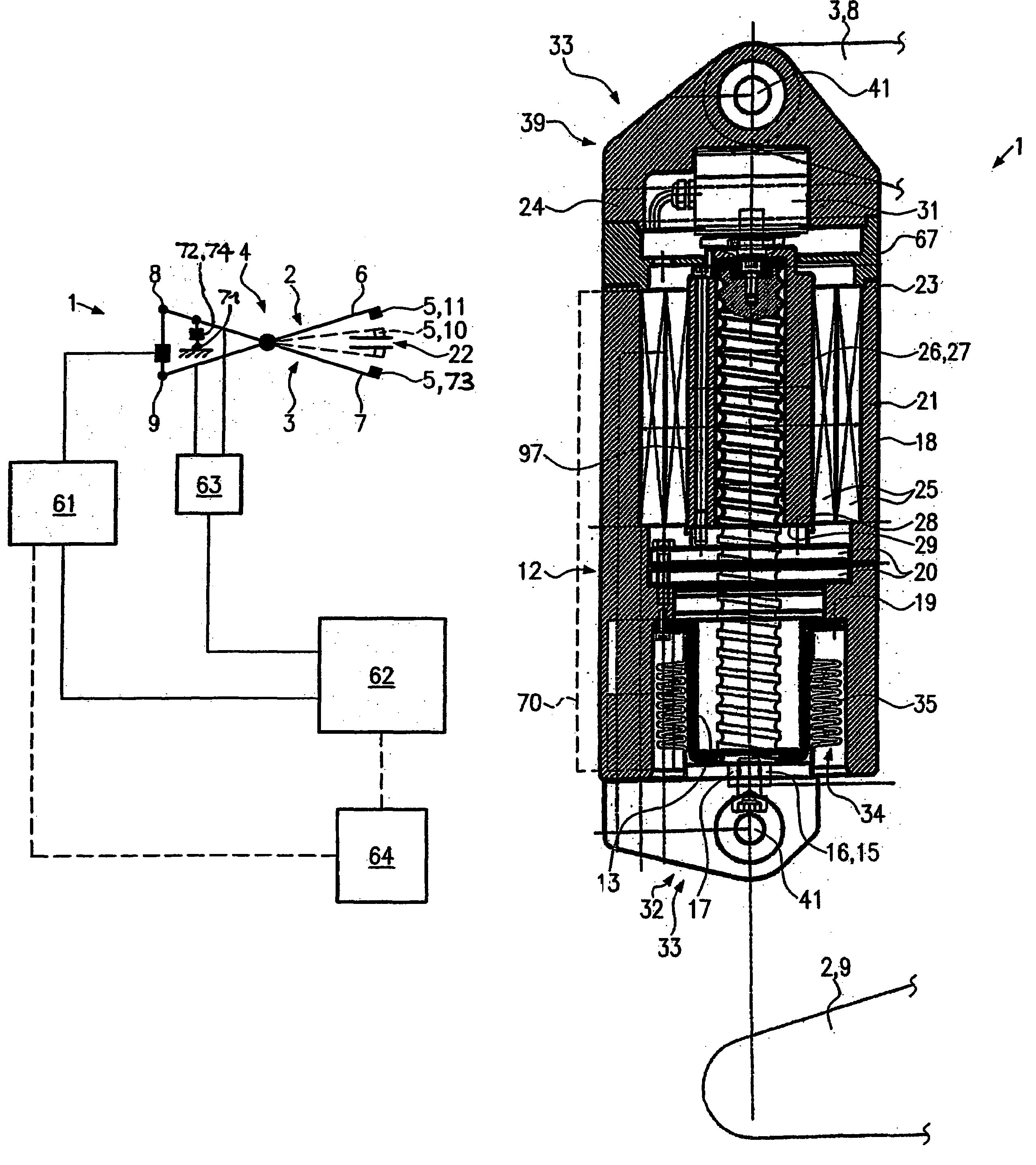
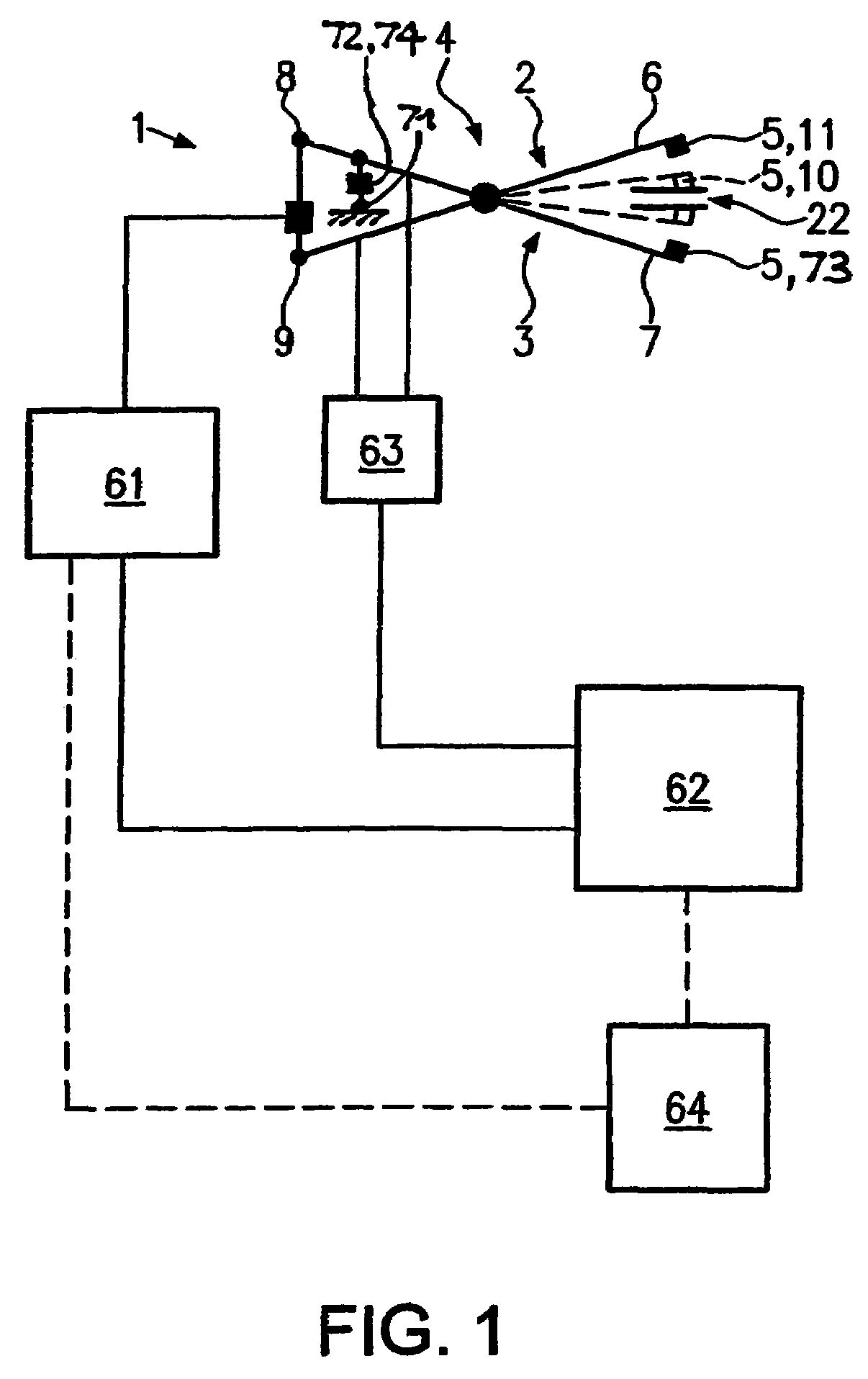
[0082]FIG. 1 shows a schematic diagram of the drive device 1 for welding tongs 4 according to the invention with a respective control. The welding tongs 4 comprise two double-armed levers 2, 3. Respective welding electrodes 5 are arranged on an end of each lever designated as welding lever end 6, 7. The drive device 1 according to the invention is arranged between the adjusting lever ends 8, 9 opposing the welding lever ends 6, 7. In FIG. 1 in the view with the drawn-through lines, the levers 2, 3 are in their standby position and in the dotted view the levers are in their welding position. In the welding position 10 an electrode power is exerted via the welding electrodes 5 onto a workpiece 22 for instance to press two sheets against each other forming the workpiece for subsequently being welded.

[0083]The two levers 2, 3 of the welding tongs 4 are connected to a welding control. This welding control supplies power to the levers and thus to the welding electrodes 5 during the weldin...


PUM

PropertyMeasurementUnit
Lengthaaaaaaaaaa

Abstract

A drive device for a pair of welding tongs having a pair of limbs, is arranged between the adjusting ends of the limbs, located opposite to the welding electrodes, for adjusting between a welding position and a standby position. In order to reduce its length, provide continuous control and monitoring, simplify the device and reduce noise, the drive device is provided with an electric motor-driven screw-thread drive with a rotating nut and a rotating spindle which is axially displaceable between an extended and a return position, the spindle being connected to an adjusting end of the limb. The drive device can be used as a main drive for a pair of welding tongs for the positioning of the limbs, or can be used as a secondary drive, for setting of a stopping position of the pair of welding tongs.

Description

FIELD OF THE INVENTION [0001]The present invention refers to a drive device for welding tongs particularly comprising a pair of limbs formed for instance as double-armed levers, said drive device being arranged substantially between two adjusting ends of the limbs or levers which are located opposite to the welding ends provided with welding electrodes for pivoting at least one limb or lever between the welding position and the standby position.BACKGROUND OF THE INVENTION[0002]Normally, welding tongs with a pneumatic drive device for generating a respective electrode power are used nowadays in industry, for instance in the automobile production. The pneumatic drive devices causes, particularly if the welding tongs are formed with a pair of limbs or double-armed levers, these limbs or levers to be moved from their standby position into their welding position, in which they oppositely press onto sheets to be welded together. Upon reaching an adequate electrode power, a welding current...

Claims


Application Information

Patent Timeline
IPC IPC(8): B23K11/11B23K11/25B23K11/31F16H25/20H02K7/06
CPCB23K11/115B23K11/253B23K11/311B23K11/314B23K11/317B23K11/318F16H25/20H02K7/06F16H25/2204F16H2025/2075
Inventor SCHMITT-WALTER, STEFANHARTMANN, ROBERT
Owner SWAC ELECTRONICS
Why Eureka
Try Eureka