Apparatus and method for inspection and testing of flat panel display substrates

a flat panel display substrate and display technology, applied in the field of electroctron optics, can solve the problems of needing to fabricate a new modulator, all three flat panel display substrate testing systems and methods described above suffer from throughput limitations that will only get worse, and achieve high voltage contrast, enhanced throughput, and easy scalable to any width substrate

Active Publication Date: 2008-10-14
MULTIBEAM CORP
View PDF18 Cites 22 Cited by
  • Summary
  • Abstract
  • Description
  • Claims
  • Application Information

AI Technical Summary

Benefits of technology

[0014]Beam-Defining Aperture—the apparatus disclosed in the first embodiment herein employs a 25 μm diameter beam-defining aperture (BDA) 505 at the exit of the electron gun. This aperture has two functions: (1) it serves to control the beam current and beam diameter at the substrate by restricting the electron trajectories transmitted to the substrate to correspond to half-angles subtended at the tip over ranges varying from 0.0°-0.8° to 0.0°-1.4°, and (2) it serves as a very low transmittance pumping barrier between the electron gun vacuum chamber and the accelerating region vacuum chamber, allowing the electron gun vacuum chamber to maintain a considerably (>100×) better vacuum than that in the accelerating region vacuum chamber.
[0038]The multi-column multi-beam technology embodied in the present invention provides a means for increasing throughput for next generation substrates (so-called “Gen-7”) as well as future, even larger, substrates. In addition, the number of beams generated by the column assembly can be increased substantially with a relatively small increase in system complexity.

Problems solved by technology

A significant disadvantage of this method is the need to fabricate a new modulator 152 for each new display design.
All three of the flat panel display substrate testing systems and methods described above suffer from throughput limitations which will only get worse as the size of display substrates continues to increase.

Method used


Image

  • Apparatus and method for inspection and testing of flat panel display substrates
  • Apparatus and method for inspection and testing of flat panel display substrates
  • Apparatus and method for inspection and testing of flat panel display substrates

Examples


first embodiment

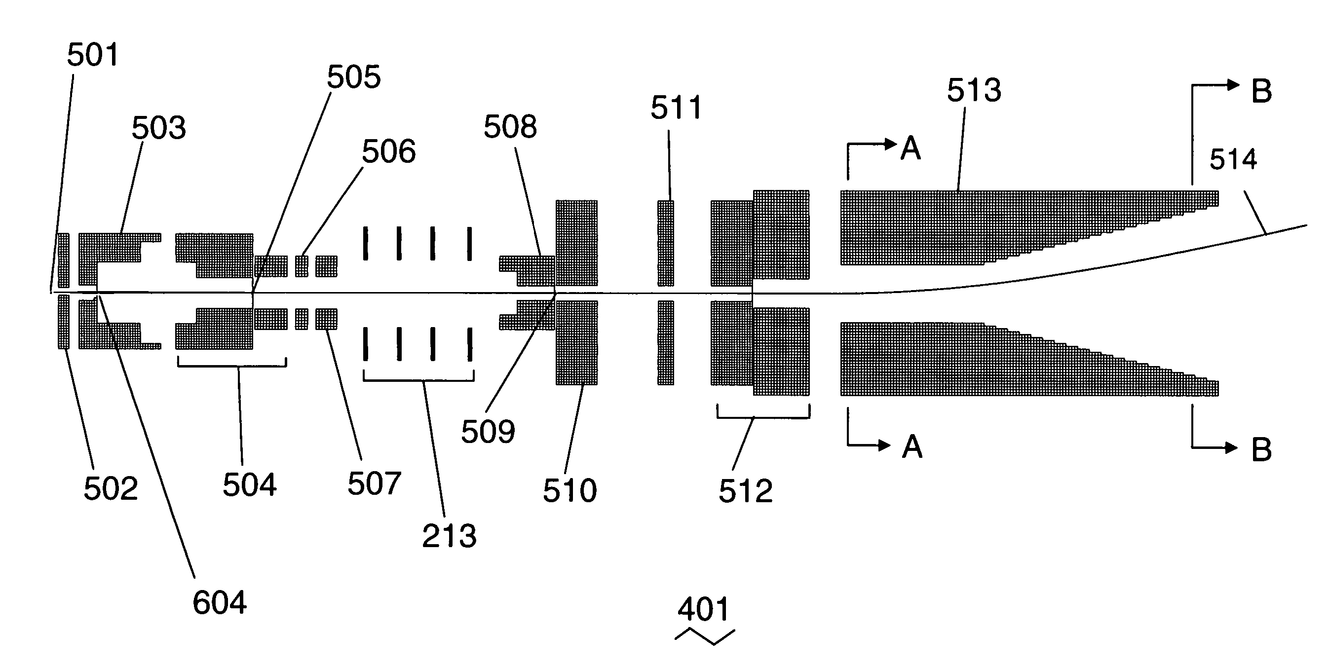
[0107]FIG. 6 shows a schematic cross-section of an electron optical column assembly in a plane containing the optical axis and the main scan axis, illustrating the 125 mm scan field (along the direction of the main scan axis) and the stitching together of scan fields from two neighboring columns. The upper optics assembly 401 is shown generating two beams, 404 and 405—in actual operation, only one of these beams would be present at any one time. Both beams 404 and 405 are shown here together to illustrate the wide scan field obtained with the present invention. The width of the scan field is determined by: (1) the width of the substrate to be inspected, and (2) the desired number of beams to be produced by the column assembly, which is determined by the tradeoff between increased cost (more beams) and lowered throughput (fewer beams). Clearly, the required scan field is then determined by:

Required Scan Width=[substrate width] / [number of columns]

A generation 7 flat panel display subs...

second embodiment

[0180]FIG. 26 shows a schematic cross-section of an electron optical column assembly in a plane containing the optical axis of one column and perpendicular to the main scan axis. Electrons are emitted by the source tip 2701 under the influence of a high electric field generated by the voltage difference between the tip 2701 and the extraction electrode 2702, typically 2700-3400 V. The suppressor electrode 2601 is typically biased negative relative to the tip 2701 to suppress electron emission from the shank (upper cylindrical portion) of the tip 2701, since this emission cannot be used to form the electron beam. The source lens comprises the extraction electrode 2702, the source lens electrode 2703, the beam-limiting aperture 2724, and the source plate 2704. Depending on the voltage applied to the source lens electrode 2703, the source lens will transmit rays through the BDA 2705 with initial half-angles at the source tip 2701 over ranges varying from 0.0°-0.8° to 0.0°-2.0°.

[0181]El...


PUM


Abstract

A charged particle optical system for testing, imaging or inspecting substrates comprises: a charged particle optical assembly configured to produce a line of charged particle beams equally spaced along a main scan axis, each beam being deflectable through a large angle along the main scan axis; and linear detector optics aligned along the main scan axis. The detector optics includes a linear secondary electron detector, a field free tube, voltage contrast plates and a linear backscattered electron detector. The large beam deflection is achieved using an electrostatic deflector for which the exit aperture is larger than the entrance aperture. One embodiment of the deflector includes: two parallel plates with chamfered inner surfaces disposed perpendicularly to the main scan axis; and a multiplicity of electrodes positioned peripherally in the gap between the plates, the electrodes being configured to maintain a uniform electric field transverse to the main scan axis.

Description

CROSS-REFERENCE TO RELATED APPLICATIONS[0001]This application claims the benefit of U.S. Provisional Application Ser. No. 60 / 608,609 filed Sep. 10, 2004 and U.S. application Ser. No. 11 / 093,000 filed Mar. 28, 2005, both incorporated by reference herein.BACKGROUND OF THE INVENTION[0002]1. Field of the Invention[0003]This invention relates to the field of electron optics, and in particular to electron beam testing of large substrates such as flat panel display substrates.[0004]2. Description of the Related Art[0005]The use of electron beams to inspect and electrically test flat panel display substrates is an established technique. The different testing strategies may be characterized by the method of obtaining the test signal from each pixel in the display: mechanical probe testing; electron-beam probe testing; and voltage imaging.[0006]Mechanical probe testing of a flat panel display substrate is illustrated in FIG. 1. During manufacture, all the signal lines 110 on the display subst...

Claims


Application Information

Patent Timeline
Patent Type & Authority Patents(United States)
IPC IPC(8): H01J37/28H01J37/147
CPCH01J9/42H01J37/09H01J37/147H01J37/244H01J37/256H01J2237/0492H01J2237/1501H01J2237/162H01J2237/188H01J2237/24475H01J2237/2448H01J2237/2594H01J2237/2817
Inventor PARKER, N. WILLIAM
Owner MULTIBEAM CORP
Why Eureka
Try Eureka