Driving circuit for hot cathode fluorescent lamps

a technology of hot cathode fluorescent lamps and driving circuits, which is applied in the direction of electric variable regulation, process and machine control, instruments, etc., can solve the problems of line voltage drop and loss, loss to both user ends and power companies, and the inability to regulate the power factor

Inactive Publication Date: 2008-10-14
ZIPPY TECH
View PDF13 Cites 3 Cited by
  • Summary
  • Abstract
  • Description
  • Claims
  • Application Information

AI Technical Summary

Benefits of technology

[0007]To achieve the foregoing object, the driving circuit for hot cathode fluorescent lamps according to the invention mainly includes a commutation unit to transform AC input cycle signals to DC cycle signals, a switch unit to divide driving power output to the hot cathode fluorescent lamps that has a duty voltage value and a valley filled power factor correction circuit which is electrically connected to the commutation unit and has a cutoff voltage value higher than the duty voltage value of the switch unit. Therefore when the voltage of the AC input cycle signals is lower than the cutoff voltage, the commutation unit cuts off conduction. As a result, the AC input cycle signals with the voltage lower than the cutoff voltage are filtered out before arriving the commutation unit. The switch unit at the rear end receives signals that have a voltage higher enough to allow the switch unit to enter an operating condition. Thus power accumulation that might otherwise occur to pierce the switch unit can be prevented.

Problems solved by technology

However the ineffective power (KVAR) causes line voltage drops and loss.
This is a loss to both the user ends and the power company.
Hence to regulate power factor is a big issue for providers of user end systems.
When an electronic device equipped with a valley filled power factor regulation circuit is in an operating condition, if the signal transmitted to the transistor switch has a voltage value lower than the duty voltage of the transistor, the transistor cannot enter the operating condition due to not sufficient voltage.
When the accumulated power reaches the limit of the transistor switch, the transistor switch will be damaged or pierced.

Method used


Image

  • Driving circuit for hot cathode fluorescent lamps
  • Driving circuit for hot cathode fluorescent lamps
  • Driving circuit for hot cathode fluorescent lamps

Examples


Embodiment Construction

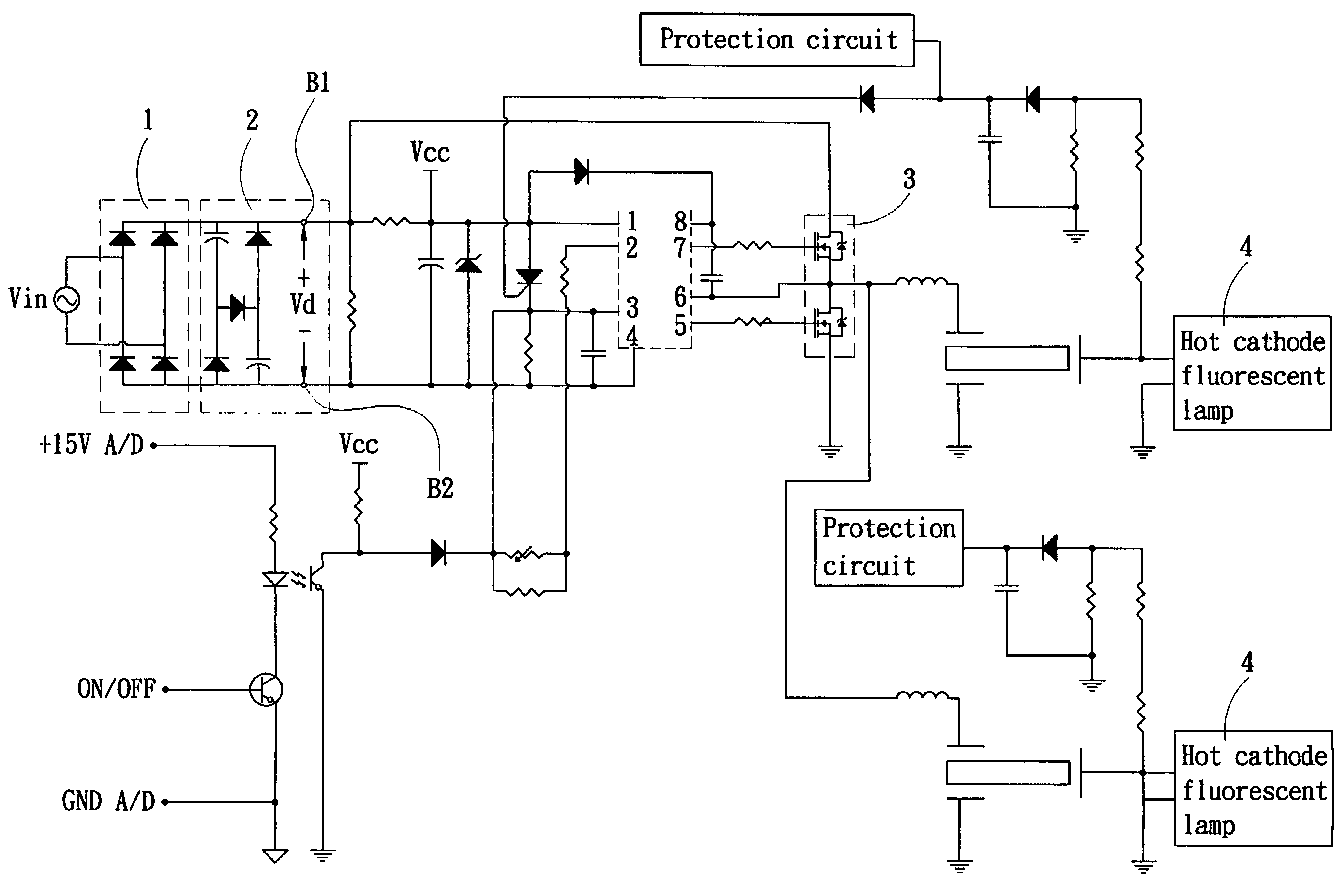
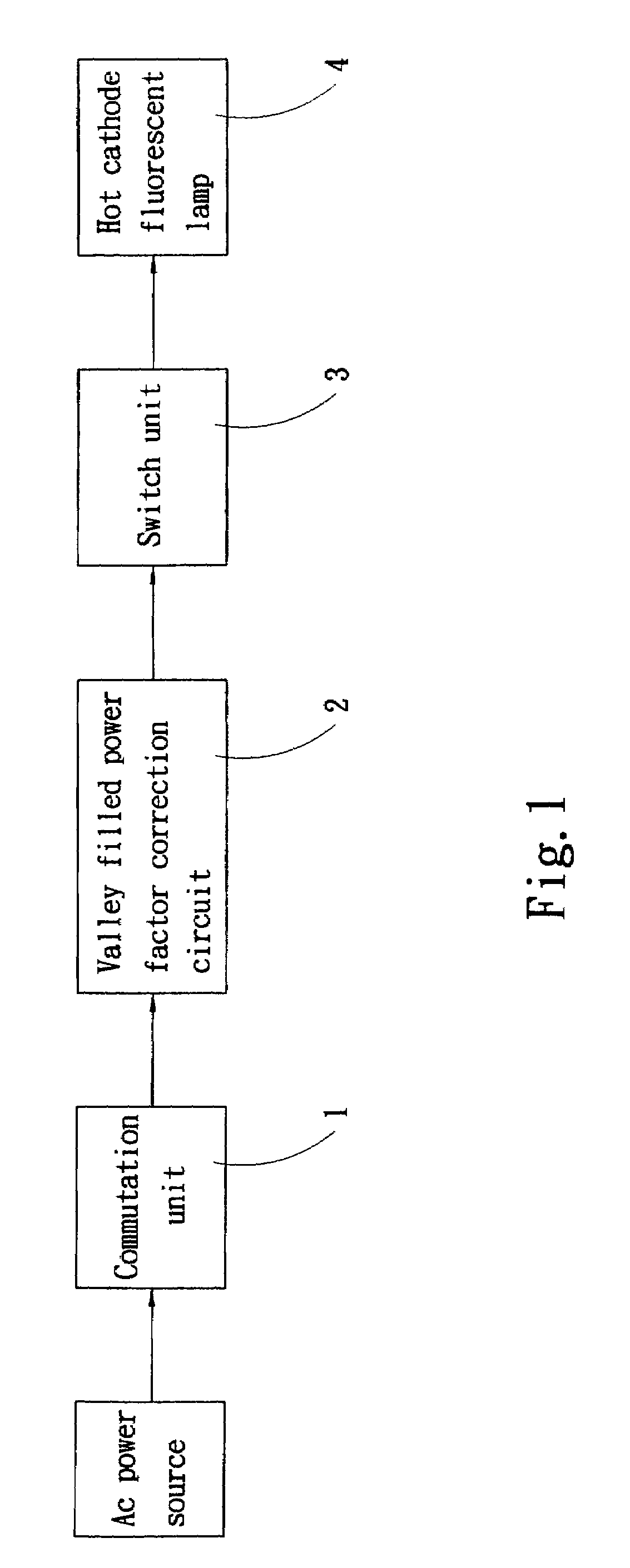
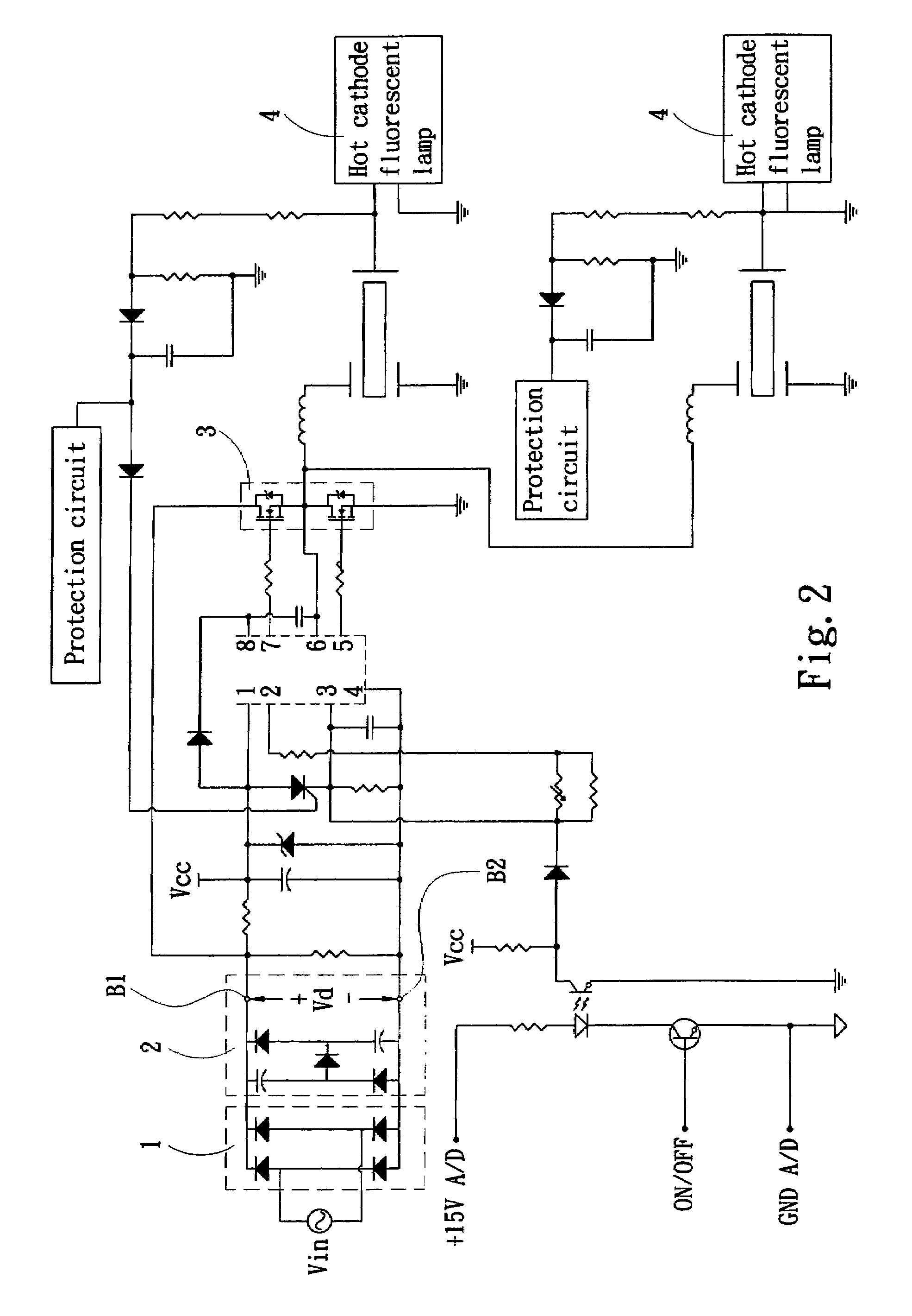
[0020]Please refer to FIGS. 1 and 2 for an embodiment of the invention. The driving circuit for a hot cathode fluorescent lamp (HCFL) 4 according to the invention mainly includes:

[0021]a commutation unit 1 to transform an AC input cycle signal Vin from an AC power source to a DC cycle signal S1 (also referring to FIGS. 5 and 6). In this embodiment the commutation unit 1 is a full bridge rectifier consisting of D1-D4. It has a first output end B1 and a second output end B2.

[0022]Table 1 below shows circuit conditions of a valley filled filter in various duty modes according to an embodiment of the invention.

[0023]

TABLE 1DutyVoltageDiode conditionCurrentmodeconditionONOFFconditionI|Vin| D5, D6OtherIin = 0;Vd = VcpILoad = IC1 + Ic2IIVcp D1, D4; Vin > 0OtherIin = ILoad;Vcs; Vd = |Vin|D2, D3; Vin IC1 = Ic2 = 0III|Vin| > Vcs;D1, D4, D7;OtherIin = ILoad − IC1;Vd = |Vin|Vin > 0IC1 = Ic2D2, D3, D7;Vin

[0024]The invention further includes a valley filled power factor correction circuit 2 to r...


PUM


Abstract

A driving circuit for hot cathode fluorescent lamps aims to filter out signals with a voltage value lower than a duty voltage value of a switch unit through a commutation unit and a valley filled power correction circuit to prevent power from accumulating and the switch unit from being pierced.

Description

FIELD OF THE INVENTION[0001]The present invention relates to a driving circuit and particularly to a driving circuit for hot cathode fluorescent lamps to filter out signals with a voltage value lower than a duty voltage of a switch unit through a commutation unit and a valley filled power factor correction circuit to prevent electricity from piercing the switch unit.BACKGROUND OF THE INVENTION[0002]The general AC transmitted through the AC distribution system of power companies usually are connected to various types of loads that include resistance loads such as incandescent lamps, ovens and the like, and many other types of loads that mostly consist of resistance and induction. Hence on electronic circuits the current phase angle is lagged behind the voltage. In general the total current provided by the power company from generators through the power transmission and distribution lines includes effective current and ineffective current. Due to different rated voltage of different l...

Claims


Application Information

Patent Timeline
Patent Type & Authority Patents(United States)
IPC IPC(8): H05B37/02
CPCH05B33/0818H05B41/2825Y02B20/346H05B47/00Y02B20/30
Inventor CHENG, YING-CHANGCHUNG, CHIN-BIAU
Owner ZIPPY TECH
Why Eureka
Try Eureka