Imaging lens and camera apparatus

a technology of imaging lens and camera body, applied in the field of imaging lenses, can solve the problems of insufficient miniaturization, high cost, and insufficient imaging lens, and achieve the effects of reducing size, weight, cost, and excellent optical performan

Active Publication Date: 2008-10-14
TIANJIN OFILM OPTO ELECTRONICS CO LTD
View PDF8 Cites 15 Cited by
  • Summary
  • Abstract
  • Description
  • Claims
  • Application Information

AI Technical Summary

Benefits of technology

[0007]An object of an illustrative, non-limiting embodiment of the invention is to provide an imaging lens which can maintain excellent optical performance, and which is reduced in size, weight, and cost, and also a camera comprising the imaging lens.
[0009]When exceeding the upper limit of conditional expression (1), it is possible to obtain a long exit pupil distance, but it is difficult to achieve miniaturization and increased wide angle of the imaging lens. When failing to satisfy the range of conditional expression (2), it is difficult to sufficiently correct lateral chromatic aberration. When exceeding the upper limit of conditional expression (3), it is difficult to extend the filed of view, and at the same time the curvature of field is increased. When being below the lower limit of conditional expression (3), the field of view can be increased, but coma aberration is increased and the image quality of a peripheral portion of an image surface is impaired.
[0012]By the satisfying the conditional expression (4′), the wide angle of the imaging lens can be held and reduction of the size of the imaging lens can be achieved.
[0016]The imaging lens may satisfy:D1 / f<1  (7)where D1 is the distance (center thickness) between the apex on the object side of the first lens and that on the image side, whereby the size of the imaging lens can be prevented from being increased.

Problems solved by technology

However, the imaging lenses disclosed in JP-A-2001-337268, JP-A-2005-181596 and JP-A-2005-321742 are insufficient in miniaturization.
The imaging lens disclosed in Japanese Patent No. 3206930 uses high-refractive index glass as the first lens, and hence has a disadvantage that the cost is high.
Therefore, the imaging lens is not suitable for use in a vehicle camera, surveillance camera, or the like which is not always used in an environment of adequate brightness.

Method used


Image

  • Imaging lens and camera apparatus
  • Imaging lens and camera apparatus
  • Imaging lens and camera apparatus

Examples


example 1

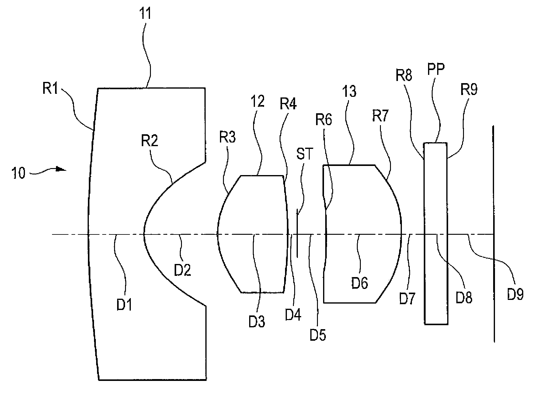
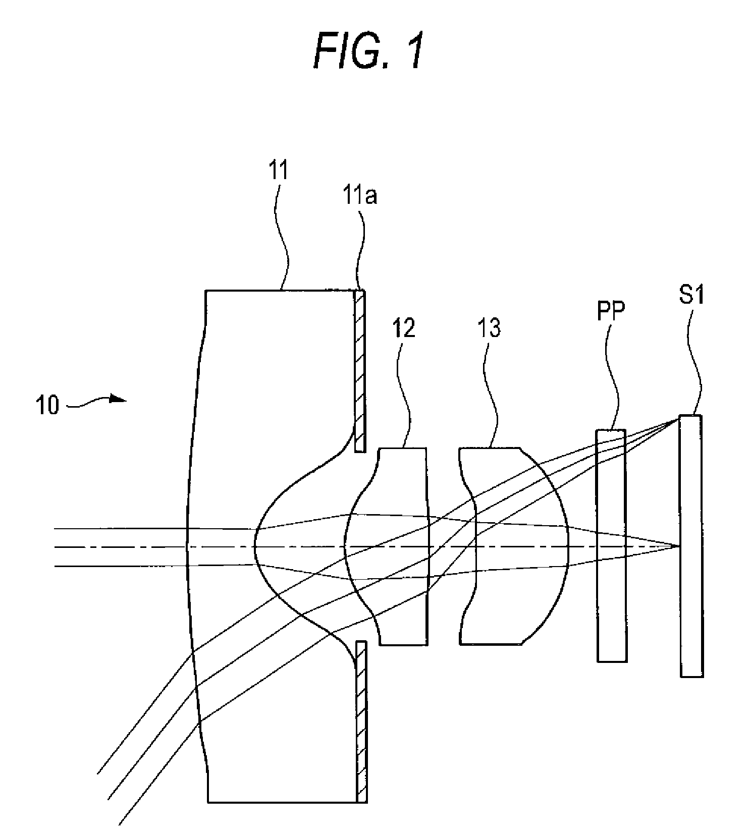
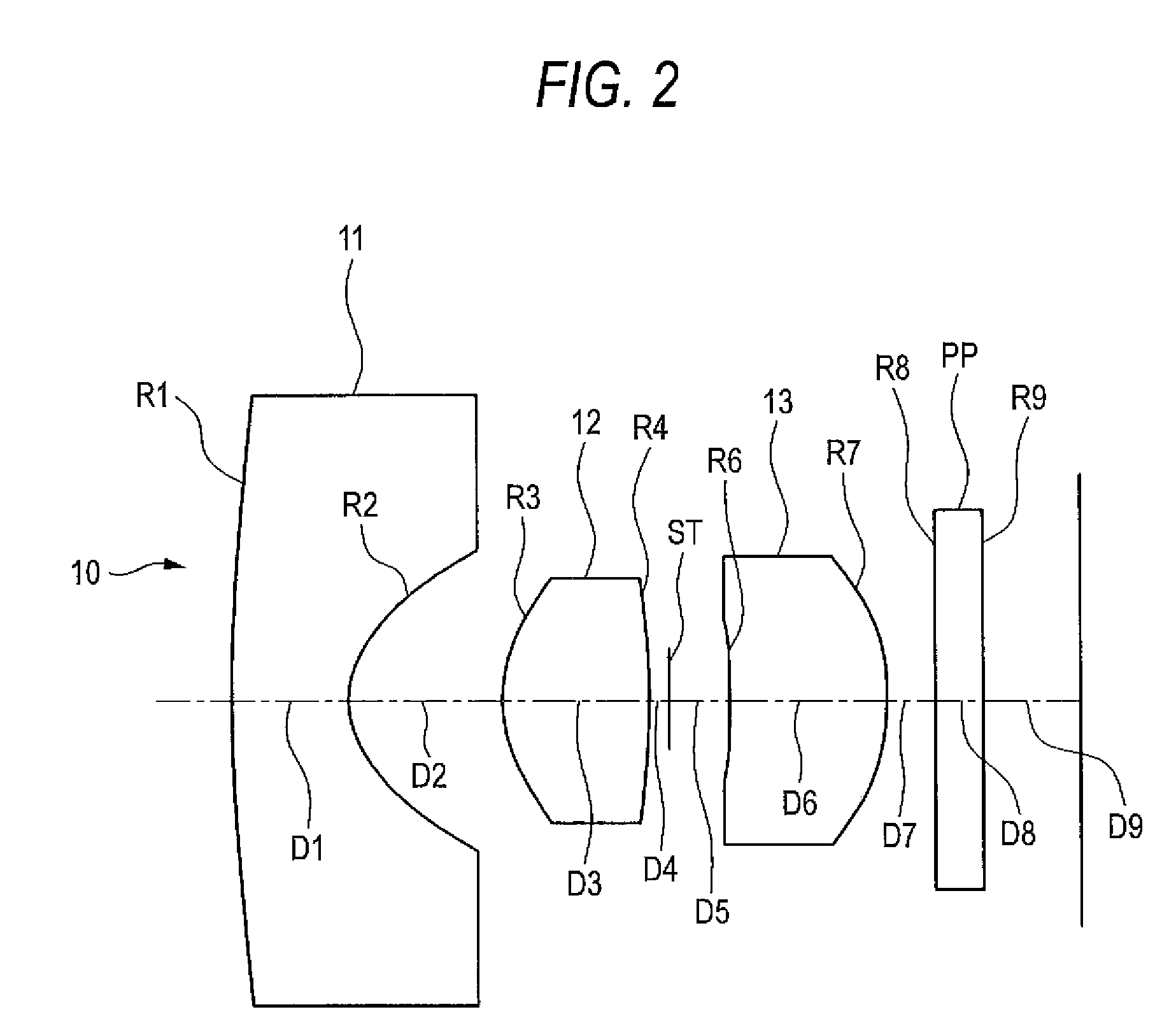
[0040]Referring to FIGS. 1 and 2, the imaging lens 10 includes sequentially from the object side a first lens 11, a second lens 12, and a third lens 13. Each of the first to third lenses 11 to 13 is configured by a bi-aspherical plastic lens having aspherical surfaces which are rotationally symmetric about the optical axis. The first lens 11 has a negative refractive power and has a meniscus shape where a convex surface is on the object side, a concave surface is on the image side, and the absolute value of the radius of curvature of the image-side surface is smaller than that of the object-side surface. A light shielding film 11a is disposed on a region outside the image-side concave surface of the first lens 11. The light shielding film 11a prevents light from entering from the outside of the effective diameter, and a ghost image from appearing on the image plane. The light shielding film 11a is a layer of an opaque coating composition which is disposed outside the effective diame...

example 2

[0048]Referring to FIG. 4, an imaging lens 20 includes sequentially from the object side a first lens 21, a second lens 22, and a third lens 23. Each of the first to third lenses 21 to 23 is configured by a bi-aspherical plastic lens. The first lens 21 has a negative refractive power and has a meniscus shape where a convex surface is on the object side, a concave surface is on the image side, and the absolute value of the radius of curvature of the image-side concave surface is smaller than that of the object-side surface. The second lens 22 has a bi-convex shape where each of the object and image side surfaces is a convex surface, and the absolute value of the radius of curvature of the object-side surface is smaller than that of the image-side surface. The third lens 23 has a positive refractive power and has a meniscus shape where a concave surface is on the object side, a convex surface is on the image side, and the absolute value of the radius of curvature of the image-side con...

example 3

[0053]Referring to FIG. 6, an imaging lens 30 includes sequentially from the object side a first lens 31, a second lens 32, and a third lens 33. Each of the first to third lenses 31 to 33 is configured by a bi-aspherical plastic lens. The first lens 31 has a negative refractive power and a meniscus shape where a convex surface is on the object side, a concave surface is on the image side, and the absolute value of the radius of curvature of the image-side concave surface is smaller than that of the object-side convex surface. The second lens 32 has a bi-convex shape where each of the object and image side surfaces is a convex surface, and the absolute value of the radius of curvature of the object-side surface is smaller than that of the image-side surface. The third lens 33 has a positive refractive power and a meniscus shape where a concave surface is on the object side, a convex surface is on the image side, and the absolute value of the radius of curvature of the image-side conv...


PUM


Abstract

An imaging lens is configured sequentially from the object side by: a first lens having a meniscus shape where a convex surface is directed to the object side; a second lens; and a positive third lens in which an image-side surface is a convex surface. The first lens, the second lens, and the third lens are configured by a bi-aspherical plastic lens. The second lens is configured by a bi-convex lens in which the absolute value of the radius of curvature of the object-side surface is smaller than that of the image-side surface. The third lens is a positive lens and a meniscus lens in which a concave surface is directed to the object side, and a convex surface is directed to the image side.

Description

BACKGROUND OF THE INVENTION[0001]1. Field of the Invention[0002]The present invention relates to an imaging lens which is suitably used in a vehicle camera, a surveillance camera, a camera for a portable telephone, or the like, and which forms an optical image on a solid-state imaging device, and also relates to a camera apparatus comprising the lens.[0003]2. Description of Related Art[0004]A vehicle camera for imaging the surrounding of a vehicle is known (for example, see JP-A-2006-168683). Such vehicle cameras include: an out-vehicle camera which is disposed outside a vehicle, and which images, for example, a blind zone of the driver's vision to assist the driving operation; and an in-vehicle camera which images a field of view identical with the driver's vision field in order to record the status of occurrence of a traffic accident or the like. In accordance with enhancement of performance and cost reduction of a solid-state imaging device, recently, vehicles having a vehicle ca...

Claims


Application Information

Patent Timeline
Patent Type & Authority Patents(United States)
IPC IPC(8): G02B9/12G02B3/02G02B9/00
CPCG02B9/12G02B13/0035
Inventor ASAMI, TARO
Owner TIANJIN OFILM OPTO ELECTRONICS CO LTD
Why Eureka
Try Eureka