Air flow rate measuring device

a technology of air flow rate and measuring device, which is applied in the direction of measurement device, volume/mass flow measurement, instruments, etc., can solve the problems of large pressure loss across the grid, deterioration of the measurement accuracy of the air flow rate measuring device, etc., and achieves high reliability, high performance, and easy deformation

Active Publication Date: 2008-10-21
HITACHI ASTEMO LTD
View PDF11 Cites 4 Cited by
  • Summary
  • Abstract
  • Description
  • Claims
  • Application Information

AI Technical Summary

Benefits of technology

[0009]For example, the above object can be achieved by a flow measuring device in which a grid includes a first grid portion and a second grid portion between the first grid portion and a passage forming component, and the second grid portion is more easily deformed than the first grid portion.
[0010]The present invention can provide an air flow rate measuring device of high performance and high reliability which reduces a pressure loss across the grid due to the load which is generated at a tightening of a hose band, prevents the deterioration of measurement accuracy of the air flow rate measuring device which is caused by the grid deformation, and enables the grid to have a configuration which achieves smaller pressure loss and high reliability.

Problems solved by technology

In the prior art, a deformation of the second rib grid leads to a deformation of the first mesh grid, and also a deformation of the second rib grid at the beginning of a tightening of a hose band or due to the radial load caused by a thermal factor causes a problem of deterioration of measurement accuracy of the air flow rate measuring device.
In addition, the second rib grid is formed to have a sufficient thickness to maintain a mechanical strength of the rib grid, which results in a large pressure loss across the grid.

Method used


Image

  • Air flow rate measuring device
  • Air flow rate measuring device
  • Air flow rate measuring device

Examples


second embodiment

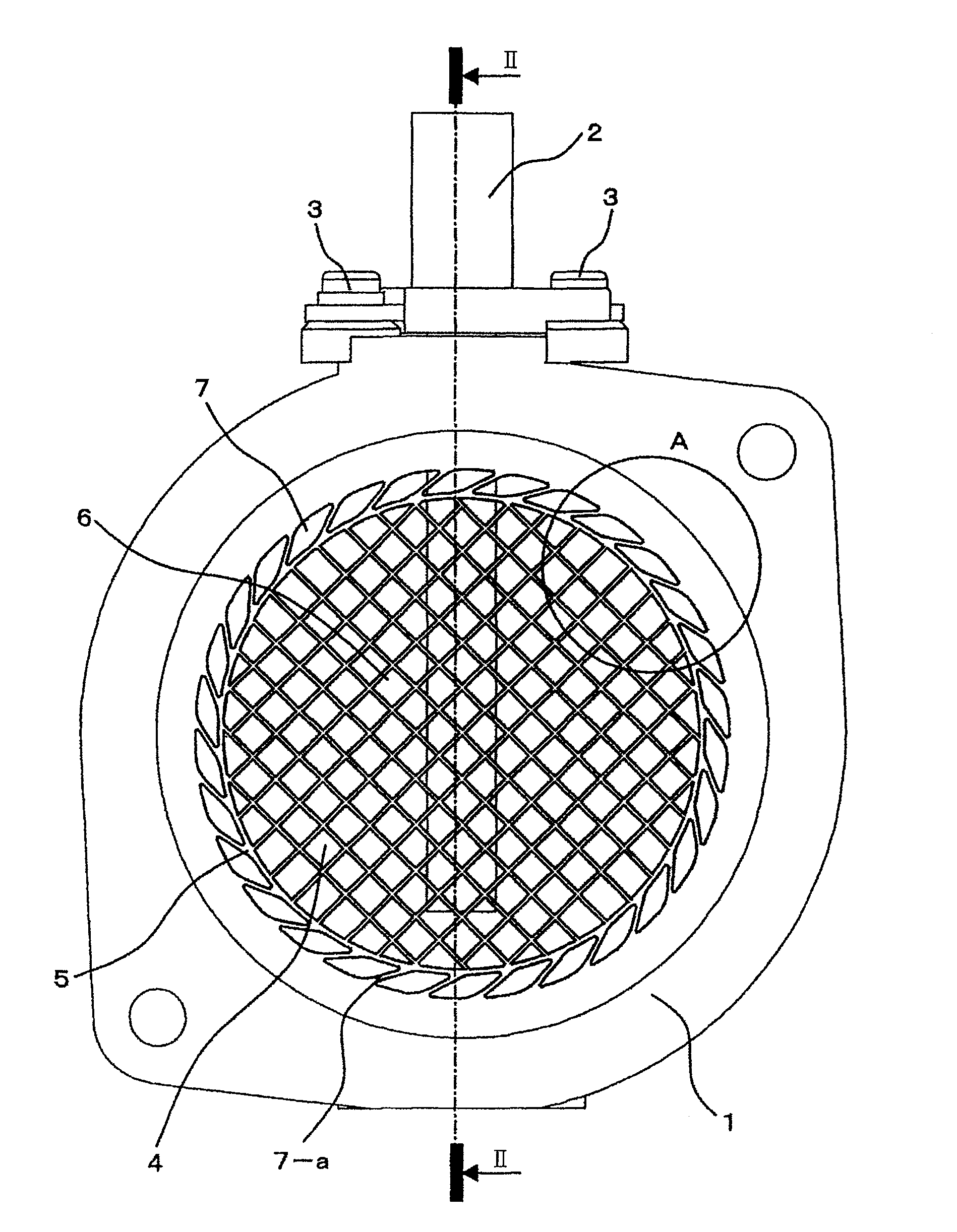
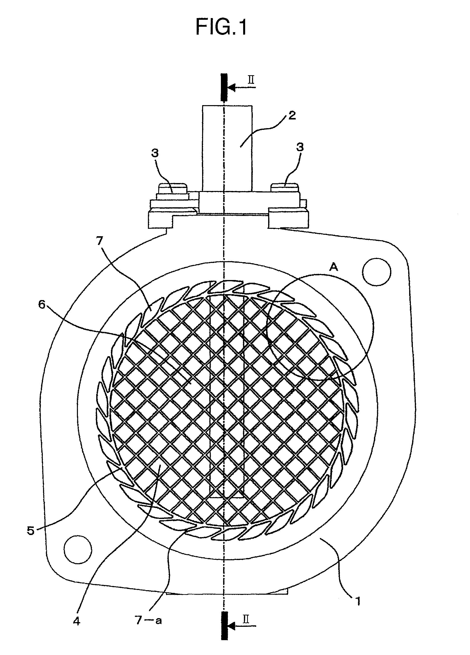
[0052]FIG. 7 shows the air flow rate measuring device according to the present invention, and illustrates only the portion corresponding to the portion A in FIG. 1.

[0053]In the second embodiment, the grid 7 provided outside the frame 5 is configured to have beams 7-a which are arranged at an acute angle 7-b of 45 degrees or less relative to the normal direction 7-i toward the center of the frame 5.

[0054]According to the above configuration, since the grid 7 is easily deformed by the radial load 11, the effect to absorb the radial load 11 can be enhanced. The more acute the angle 7-b is, the more easily deformed the grid 7 is by the radial load 11, which also enhances the effect to absorb the radial load 11. As a result, deterioration of measurement accuracy of the air flow rate measuring device can be prevented.

third embodiment

[0055]FIG. 8 shows the air flow rate measuring device according to the present invention, and illustrates only the portion corresponding to the portion A in FIG. 1.

[0056]In the third embodiment, the grid 7 provided outside the frame 5 is configured to have beams 7-a which are arranged at an tilted angle relative to the normal direction 7-i which extends toward the center of the frame 5. Each of the beams 7-a has side surfaces which are tilted at different angles 7-f and 7-g respectively. The angles 7-f and 7-g are set so that the width of each of the beams 7-a tapers from the outer peripheral toward the center of the frame 5. That is, each of the beams 7-a has tilted side surfaces at different angles 7-f and 7-g respectively, and the angles 7-e and 7-f are set so that the width at both ends of each of the beams 7-a tapers from the body 1 toward frame 5. In other words, the grid 7 is configured to have beams 7 so that the width 7-k of the beams 7-a on the frame 5 side is less than th...

fourth embodiment

[0059]FIG. 9 shows the air flow rate measuring device according to the present invention, and illustrates only the portion corresponding to the portion A in FIG. 1.

[0060]In the fourth embodiment, the grid 7 provided outside the frame 5 is configured to have the beams 7-a having a bent portion 7-h.

[0061]According to the above configuration, since the bent portion 7-h is easily deformed by the radial load 11, and the beams 7-a are more deformable, the effect to absorb the radial load 11 can be enhanced. As a result, deterioration of measurement accuracy of the air flow rate measuring device can be prevented.


PUM


Abstract

An air flow rate measuring device is provided in which a pressure loss across a grid therein due to the load which is generated when a hose band is tightened is reduced and deterioration of its measurement accuracy due to the grid deformation is prevented. The grid is configured to have a grid portion which absorbs deformation at the outer periphery thereof, and another grid portion which does not absorb deformation at the inner periphery thereof. In order to make the grid portions independent of each other, the grid is provided with a frame, and the mesh grid inside of the frame which maintains a rectifying effect, prevents the deterioration of the measurement accuracy, and does not absorb deformation, and the grid outside of the frame absorbs deformation.

Description

BACKGROUND OF THE INVENTION[0001]The present invention relates to an air flow rate measuring device, and in particular to an air flow rate measuring device for measuring an air flow which is supplied to an internal combustion engine of an automobile.[0002]Generally, a metal mesh, an aluminum honeycomb or a plastic is used to form a rectifier grid of an air flow rate measuring device. In the case of a plastic molding, as described in Japanese Patent No. 3245362, in order to maintain a mechanical strength and prevent deformation and deterioration of the grid, the plastic molding is configured to include a first mesh grid having a first thickness and spaces therein and a second rib grid having a thickness larger than the first one and spaces wider than in the first mesh grid, and the first mesh grid and the second rib grid are integrally formed with one another. Also, in order to address a load applied toward a center of a body of a device from an outer periphery thereof, a grid config...

Claims


Application Information

Patent Timeline
Patent Type & Authority Patents(United States)
IPC IPC(8): G01F1/68
CPCG01F1/6842G01F15/00G01F15/18
Inventor KOZAWA, MASAYUKIIIDA, MAKOTOYASUKAWA, AKIOHIKOTA, MARIMIKI, TAKAHIRO
Owner HITACHI ASTEMO LTD
Why Eureka
Try Eureka