
Spectacle lens supply system, spectacle wearing parameter measurement apparatus, spectacle wearing test system, spectacle lens, and spectacle

a technology of parameter measurement and supply system, which is applied in the field ofspectacle lens supply system, can solve the problems of not providing optimal and dedicated spectacle lenses to respective spectacle wearers, unable to effectively use figures, and unable to process, so as to achieve high accuracy and improve measurement speed. , the effect of high accuracy

Inactive Publication Date: 2008-10-28
HOYA CORP
View PDF14 Cites 25 Cited by
  • Summary
  • Abstract
  • Description
  • Claims
  • Application Information

AI Technical Summary

Benefits of technology

The present invention aims to provide a spectacle lens supply system that can supply an optimal and dedicated spectacle lens or spectacle for each of spectacle wearers. The system should measure and calculate various parameters required for designing a spectacle lens or spectacle based on the unique shape of the spectacle frame of each wearer. Additionally, the system should be able to verify the wearing state of the spectacle and manufacture a refractive power correction spectacle lens accordingly. The technical effects of the invention include improved vision, better fit, and enhanced comfort for spectacle wearers.

Problems solved by technology

However, the above-described conventional system is a system to place or receive an order for a spectacle lens, and does not measure the spectacle wearing parameter in accordance with the respective spectacle wearer, does not perform an optical designing using the measured value, does not process, and does not provide an optimal for and dedicated spectacle lens to the respective spectacle wearers.
According to the conventional apparatus described in Patent document 2, mainly, the distance vision inter-pupil distance, the spectacle frame wearing angle, and the inter-vertex distance are measured, however, the inter-vertex distance out of these does not consider a three dimensional shape of the spectacle frame, so that it can not be said to be the distance vision spectacle wearing distance as a spectacle wearing parameter, practically, and the figure can not be effectively used.
Furthermore, there is no apparatus capable of performing a measurement by selecting a spectacle wearing parameter required to manufacture a refractive power correction spectacle lens (progressive power lens, multifocal lens, single vision lens for near vision, single vision lens, and so forth) in accordance with the prescription of each spectacle wearer.

Method used


Image

  • Spectacle lens supply system, spectacle wearing parameter measurement apparatus, spectacle wearing test system, spectacle lens, and spectacle
  • Spectacle lens supply system, spectacle wearing parameter measurement apparatus, spectacle wearing test system, spectacle lens, and spectacle
  • Spectacle lens supply system, spectacle wearing parameter measurement apparatus, spectacle wearing test system, spectacle lens, and spectacle

Examples


Embodiment Construction

[0090]Hereinafter, a best mode to implement the present invention will be described based on drawings.

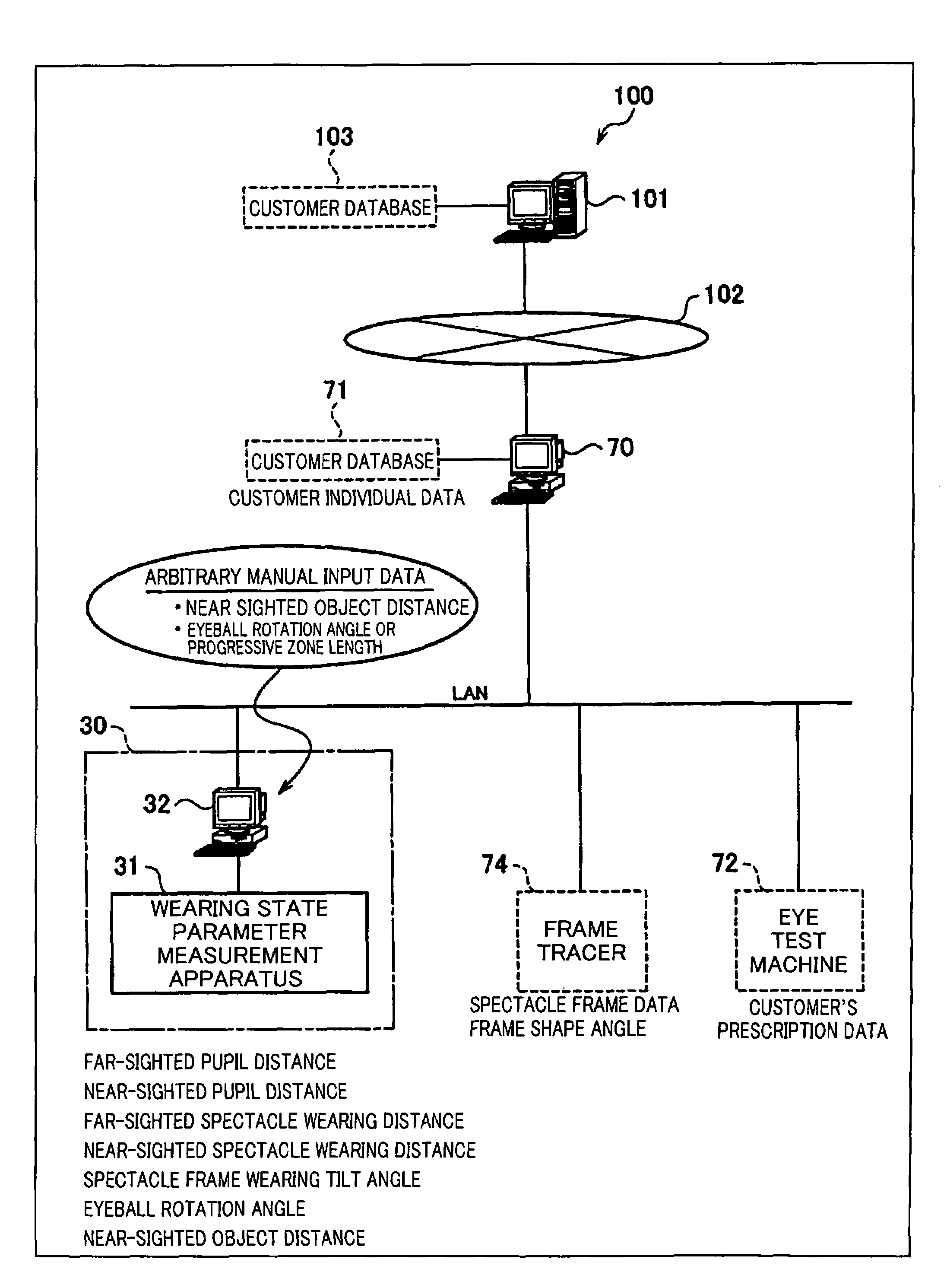
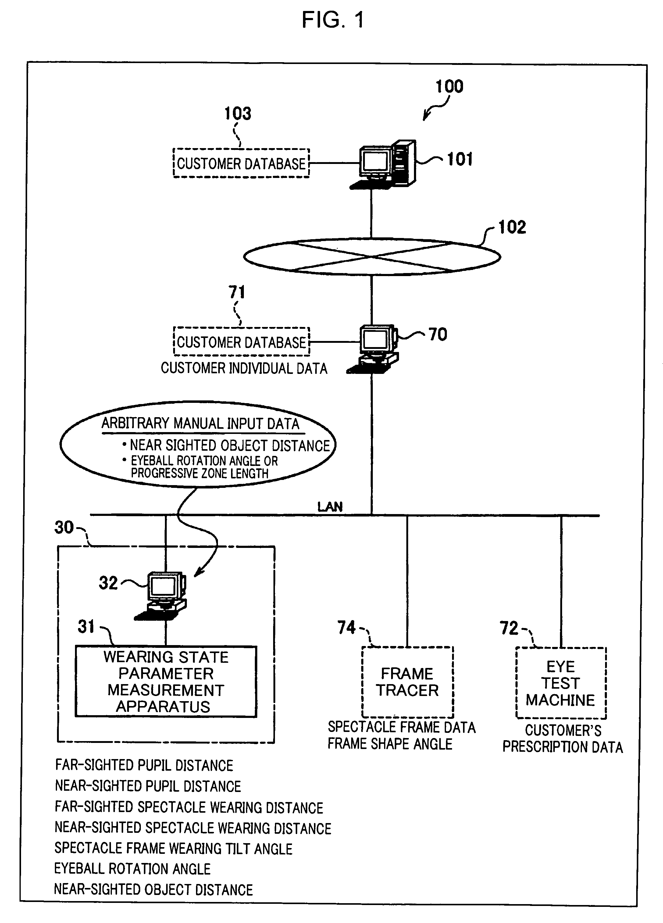
[0091]FIG. 1 is a communication circuit diagram showing an embodiment of a spectacle lens supply system, a spectacle wearing parameter measurement apparatus, and a spectacle wearing test system according to the present invention. As shown in FIG. 1, a spectacle lens supply system 100 is composed of a spectacle store terminal 70 serving as an order-placement side computer set at a spectacle store, an eye clinic, an individual, or so forth; a factory server 101 serving as a manufacturing side computer set at a spectacle lens manufacturing side such as a factory of a spectacle lens manufacturer; and a spectacle wearing parameter measurement apparatus 30 measuring a spectacle wearing parameter of a spectacle wearer and connected to the spectacle store terminal 70.

[0092]It is structured such that the spectacle store terminal 70 and the factory server 101 are connected to each other in an...


PUM


Abstract

Aims to enable to supply an optimal and dedicated spectacle lens or spectacle for each spectacle wearer, and also to verify a spectacle wearing state appropriately.A spectacle wearing parameter measurement system, sets a spectacle wearer to be in a distance vision state or a near vision state in which, in the near vision state, at least, one of an eyeball rotation angle and a near vision target distance is changeable optionally; takes an image of the spectacle wearer set in the distance vision state or near vision state by an image pickup device; imports the image; and measures and calculates a spectacle wearing parameter based on the image. A server computer of a factory received the image uses the image data to manufacture a spectacle lens or a spectacle. Further, a spectacle wearing test system verifies whether or not a spectacle wearing state is appropriate based on a figure obtained by a comparison comparing a spectacle wearing parameter measured at present time after manufacturing the spectacle and the spectacle wearing parameter before manufacturing the spectacle.

Description

TECHNICAL FIELD[0001]The present invention relates to a spectacle lens supply system, and particularly, to a spectacle lens supply system in which a computer set at an order-placement side of a spectacle lens or a spectacle and a computer set at a manufacturing side of the spectacle lens or the spectacle are connected in an information exchangeable manner.[0002]Further, the present invention relates to a spectacle wearing parameter measurement apparatus taking an image of a spectacle wearer wearing the spectacle to measure a variety of spectacle wearing parameters required to manufacture the spectacle from the image and the spectacle lens and the spectacle manufactured based on the spectacle wearing parameters measured by the measurement apparatus.[0003]Still further, the present invention relates to a spectacle wearing test system verifying a spectacle wearing state by comparing a spectacle wearing parameter measured in advance and stored in a customer database and a spectacle wear...

Claims


Application Information

Patent Timeline
Patent Type & Authority Patents(United States)
IPC IPC(8): A61B3/14A61B3/10
CPCA61B3/10A61B3/112G02C13/003G02C13/005
Inventor AKIYAMA, HISANORIJINBO, MASAHIROUENO, YASUNORI
Owner HOYA CORP
Learn More