Motor driving control device
a control device and motor technology, applied in the direction of motor/generator/converter stopper, dynamo-electric gear control, motor/generator/converter stopper, etc., can solve the problem of inability to accurately perform polarity checking, the estimation technique cannot apply to the direction of the d axis estimation, and the inability to estimate whether the direction of the d axis lies within the rang
- Summary
- Abstract
- Description
- Claims
- Application Information
AI Technical Summary
Benefits of technology
Problems solved by technology
Method used
Image
Examples
first embodiment
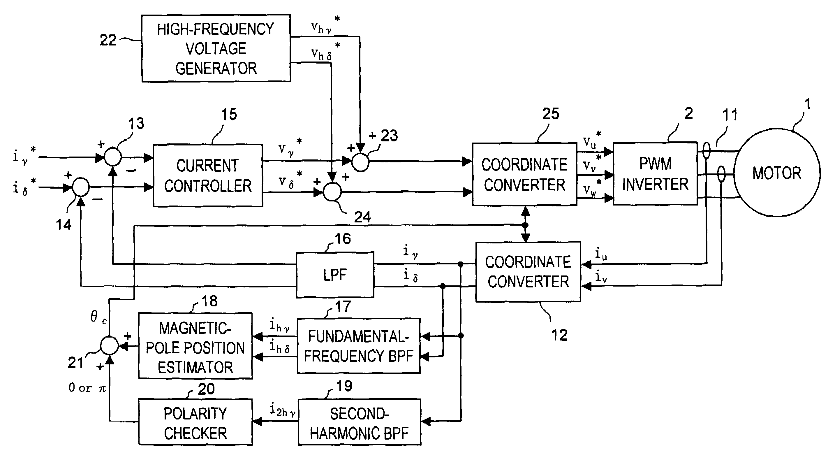
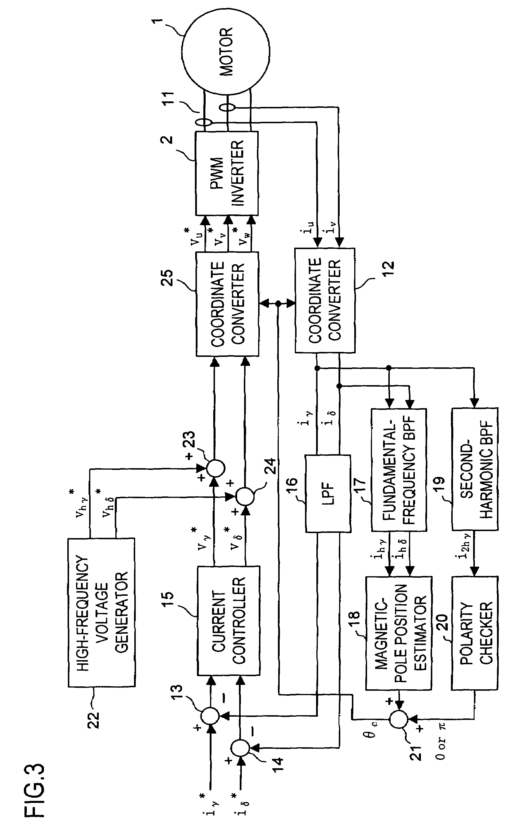
[0103]FIG. 3 is a configuration block diagram of the motor drive system of a first embodiment of the present invention. The driving control device of this embodiment is composed of a current detector 11, a coordinate converter 12, subtracters 13 and 14, a current controller 15, an LPF (low-pass filter) 16, a fundamental-frequency BPF (band-pass filter) 17, a magnetic-pole position estimator 18, a second-harmonic BPF (band-pass filter) 19, a polarity checker 20, an adder 21, a high-frequency voltage generator 22, an adder 23, an adder 24, and a coordinate converter 25. The individual functional blocks of the driving control device of this embodiment and all the embodiments described hereinafter can freely use, whenever necessary, all the values generated within the driving control device.
[0104]The current detector 11 is implemented with, for example, a Hall device, and detects the U-phase current iu and the V-phase current iv of the motor current Ia fed from the PWM inverter 2 to the...
second embodiment
[0159]Next, a second embodiment of the present invention will be described. FIG. 25 is a configuration block diagram of the motor drive system of the second embodiment. The driving control device of this embodiment differs from the driving control device shown in FIG. 3 only in that a second-harmonic BPF 19 and a polarity checker 20 shown in FIG. 3 are replaced with a second-harmonic BPF 19a and a polarity checker 20a. In other respects, the driving control device of this embodiment is the same as the driving control device (of the first embodiment) shown in FIG. 3. In FIG. 25, such functional blocks as are found also in FIG. 3 are identified with the same reference numerals, and their explanations in principle will not be repeated.
[0160]The second-harmonic BPF 19a shown in FIG. 25 realizes not only the function of the second-harmonic BPF 19 shown in FIG. 3 that extracts the second-harmonic-extracted γ-axis current i2hγ but also the function of extracting the second-harmonic-extract...
third embodiment
[0182]Next, a third embodiment of the present invention will be described. FIG. 28 is a configuration block diagram of the motor drive system of the third embodiment. The driving control device of this embodiment differs from the driving control device shown in FIG. 3 only in that a polarity checker 20 and a high-frequency voltage generator 22 shown in FIG. 3 are replaced with a polarity checker 20b and a high-frequency voltage generator 22b. In other respects, the driving control device of this embodiment is the same as the driving control device (of the first embodiment) shown in FIG. 3. In FIG. 28, such functional blocks as are found also in the figures (e.g. FIG. 3) of the already-described embodiments are identified with the same reference numerals, and their explanations in principle will not be repeated.
[0183]As is the case with the high-frequency voltage generator 22 shown in FIG. 3, the high-frequency voltage generator 22b generates high-frequency voltages vhγ* and vhδ* com...
PUM
 Abstract
Description
Claims
Application Information
 - R&D
- Intellectual Property
- Life Sciences
- Materials
- Tech Scout
- Unparalleled Data Quality
- Higher Quality Content
- 60% Fewer Hallucinations
Browse by: Latest US Patents, China's latest patents, Technical Efficacy Thesaurus, Application Domain, Technology Topic, Popular Technical Reports.
© 2025 PatSnap. All rights reserved.Legal|Privacy policy|Modern Slavery Act Transparency Statement|Sitemap|About US| Contact US: help@patsnap.com


