Method and device for shaping workpieces

a technology for shaping workpieces and workpieces, applied in the direction of shaping safety devices, metal-working feeding devices, measuring/indicating equipment, etc., can solve the problems of prolonging the setup time, laborious and time-consuming, and high setup costs, and achieves rapid setup of the machine and high degree of process reliability

Active Publication Date: 2008-11-04
LANGENSTEIN & SCHEMANN
View PDF7 Cites 0 Cited by
  • Summary
  • Abstract
  • Description
  • Claims
  • Application Information

AI Technical Summary

Benefits of technology

[0011]The object of the invention, therefore, is to propose a method and a device for shaping workpieces by which the referenced disadvantages may be at least partially overcome. ...

Problems solved by technology

This is rather laborious and time-consuming, and the setup process is consequently expensive.
This prolongs the setup time and lowers productivity.
Furthermore, over the course of time the tool may loosen during the shaping process, which is particularly the case for percussive forging die shaping machines.
This also prolongs the setup time and results in corresponding forfeiture of productivity of the unit.
However, this is achieved at the expense of process reliability or tool wear, since the positioning of the un-machined workpiec...

Method used


Image

  • Method and device for shaping workpieces
  • Method and device for shaping workpieces

Examples


Embodiment Construction

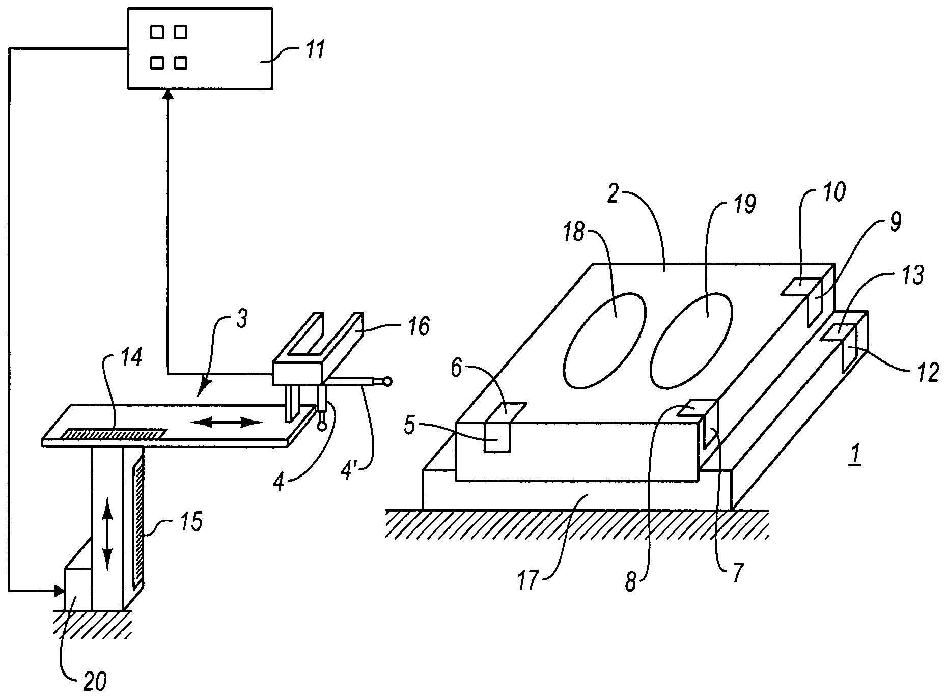
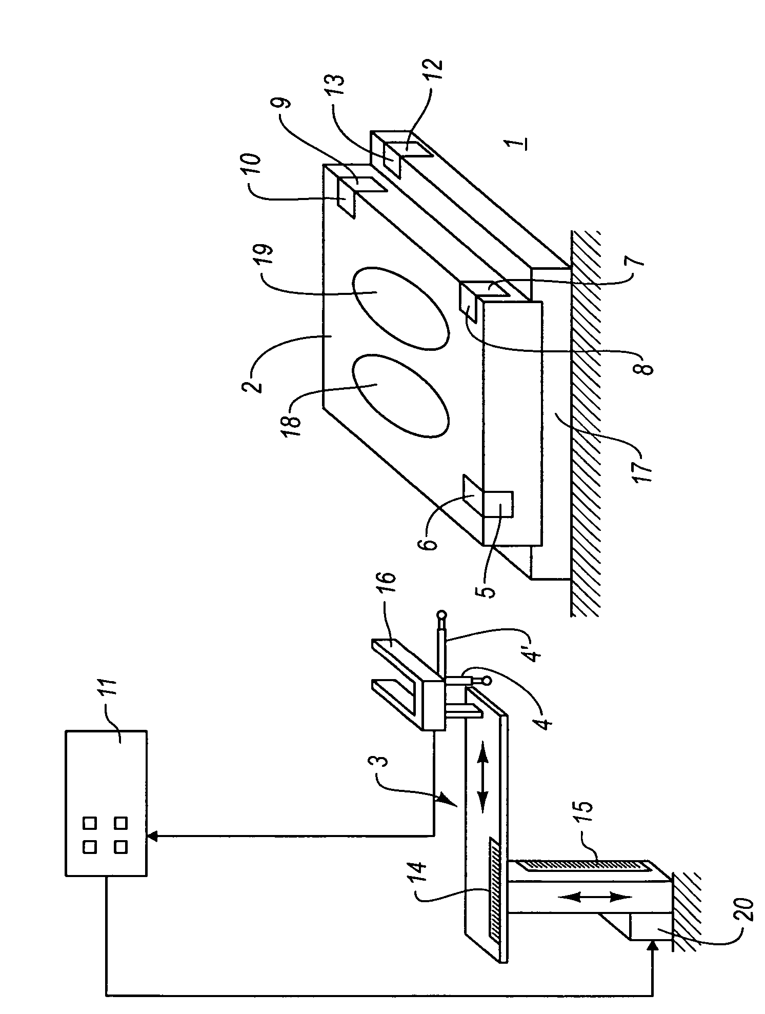
[0043]FIG. 1 shows only in a very schematic fashion a shaping machine 1 having a mounting 17 which clamps a tool 2. It is indicated, also only in a very schematic fashion, that the tool 2 has gravures 18, 19 which during the shaping process deform a workpiece (not illustrated) in such a way that it assumes a desired shape.

[0044]A handling device 3 provided with a gripper 16 is used to insert the un-machined workpieces into the tool 2 of the shaping machine 1 and to convey the workpieces after the shaping process is completed. The workpiece is handled by the gripper 16. The handling device 3 has position measurement systems 14 and 15, which likewise are illustrated in the figure only in a very schematic fashion. The handling device 3 is connected to an evaluating means 11 which actuates a drive 20 for the axes of the handling device 3. In this manner, the gripper 16 can be moved by means of the handling device 3 into the positions necessary to position the workpiece.

[0045]It is parti...


PUM


Abstract

The invention relates to a method for operating a shaping machine (1) having a tool (2), in particular a shaping machine having a shaping tool, in which the workpiece is handled by means of a handling device (3) during the manufacturing process. To improve the production process, the invention provides that before machining of workpieces on the shaping machine (1), the position and/or orientation of the tool (2) is/are determined by approaching at least one reference surface (5, 6, 7, 8, 9, 10) on the tool (2) with a handling device (3) equipped with at least one sensor (4, 4′), transmitting the determined positions of the reference surfaces (5, 6, 7, 8, 9, 10) to an evaluating means (11), and determining in the evaluating means (11) the position and orientation of the tool (2). The invention further relates to a shaping machine.

Description

BACKGROUND OF THE INVENTION[0001]1. Field of the Invention[0002]The invention relates to a method and a device for shaping workpieces.[0003]2. Background and Related Art[0004]To manufacture components by cold or warm shaping, for example by forging, shaping machines are used in which shaping tools are placed, in particular percussive shaping machines such as hammers, crank presses, and screw presses, and in particular flywheel screw presses. The shaping process is performed on an un-machined workpiece inserted into the tool by pressing or striking the tools together, thereby bringing the workpiece into its desired final shape.[0005]The manufacturing process is automated by the use of handling devices, in particular manipulators and industrial robots, for handling the workpieces. These handling devices take the un-machined workpiece, in a first step usually from a hopper, and position the workpiece between the parts of the tool, usually having a two-piece design, which is placed in t...

Claims


Application Information

Patent Timeline
IPC IPC(8): B21D43/00B21J13/08B21J13/10B23Q17/22G05B19/401
CPCB21J13/08B21J13/085B21J13/10B23Q17/2233G05B19/4015G05B2219/39105G05B2219/50027Y02P90/02
Inventor BAUERSACHS, LOTHARBARNICKEL, HARALD
Owner LANGENSTEIN & SCHEMANN
Why Eureka
Try Eureka