Control system for internal combustion engine

a control system and internal combustion engine technology, applied in the direction of electric control, machines/engines, liquid fuel feeders, etc., can solve the problems of increasing the amount of gasoline injection and so as to suppress the delay in the flow of fuel, improve the response of torque during acceleration, and suppress the effect of the delay

Inactive Publication Date: 2008-11-04
TOYOTA JIDOSHA KK
View PDF15 Cites 7 Cited by
  • Summary
  • Abstract
  • Description
  • Claims
  • Application Information

AI Technical Summary

Benefits of technology

[0007]The present invention was made in order to solve such problem as mentioned above, and it is an object of the invention to provide a control system of an internal combustion engine which injects a main fuel into an air intake port, the control system being able to improve response of torque during acceleration.
[0011]According to a first aspect of the present invention, it is possible, by supplying the hydrogen that does not adhere to a port during acceleration, at least as part of a fuel, to suppress a delay in a flow of the fuel into a cylinder and thus to improve response of torque during acceleration.
[0012]According to a second aspect of the present invention, since an adding rate of the hydrogen that does not adhere to a port during acceleration is increased, it is possible to suppress a delay in a flow of a fuel into a cylinder and thus to improve response of torque during acceleration.

Problems solved by technology

During acceleration, therefore, an abrupt increase in the amount of gasoline injection augments a delay in supply of the gasoline to the inside of the cylinder due to an increase in the amount of gasoline adhering to the port.
Therefore, in the internal combustion engines injecting the main fuel such as gasoline into an air intake port, as in the above conventional internal combustion engine, there is the problem that the response of torque deteriorates during acceleration.

Method used


Image

  • Control system for internal combustion engine
  • Control system for internal combustion engine
  • Control system for internal combustion engine

Examples


first embodiment

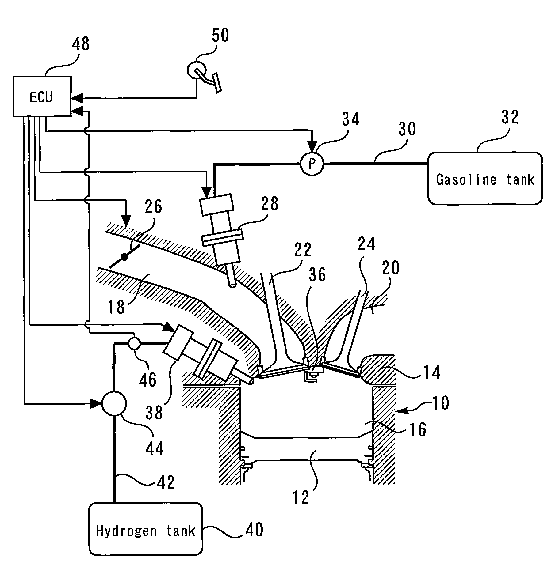
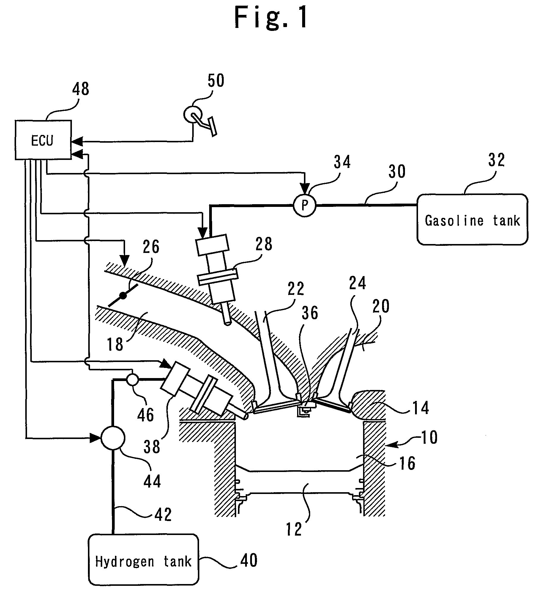
[0018]FIG. 1 is a diagram explaining a configuration of an internal combustion engine 10 in a first embodiment of the present invention. The internal combustion engine 10 has a piston 12 that reciprocates inside a cylinder of the engine. The internal combustion engine 10 also has a cylinder head 14. A combustion chamber 16 is formed between the piston 12 and the cylinder head 14. An air intake passageway 18 and an exhaust passageway 20 are communicated with the combustion chamber 16. An air intake valve 22 and an exhaust valve 24 are disposed in the air intake passageway 18 and the exhaust passageway 20, respectively. A throttle valve 26 is also provided in the air intake passageway 18. The throttle valve 26 is an electronically controlled throttle valve whose throttle angle position can be controlled independently of an accelerator angle position.

[0019]A gasoline injection valve 28 for injecting the gasoline that is a main fuel, into the air intake port, is provided in the air inta...

second embodiment

[0035]Next, a second embodiment of the present invention will be described referring to FIGS. 4A to 4F.

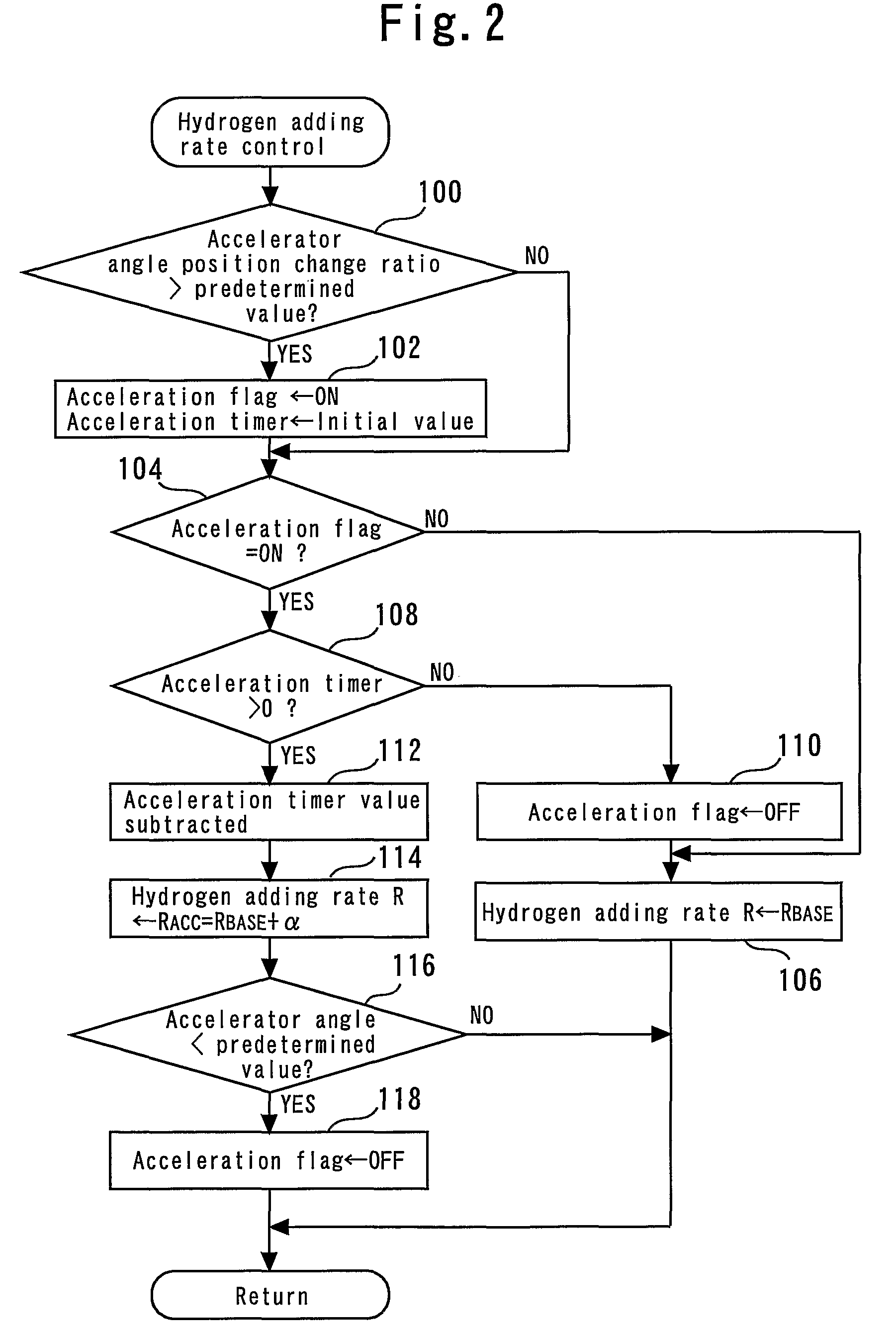
[0036]A system of the present embodiment is realized by making an ECU 48 execute a routine similar to that of FIG. 2, by use of the system configuration of the above described first embodiment. More specifically, processing in the routine similar to that of FIG. 2 is essentially the same as the processing routine shown in FIG. 2, except that a setting of an acceleration incremental value “β” of a hydrogen adding ratio differs from the setting of the acceleration incremental value “α” in the above described first embodiment. For this reason, description based on a flowchart will be omitted hereinafter and a description will be given of setting an acceleration mode hydrogen adding rate “RAcc” in the present second embodiment referring to FIGS. 4A to 4F.

[0037]FIGS. 4A to 4F are timing charts showing an example of the operation implemented by the system of the present embodiment. FIGS....


PUM


Abstract

In order that the acceleration mode hydrogen adding rate “RAcc” used during acceleration increases above the hydrogen adding base rate “RBase” predefined according to a particular operating state, the acceleration mode hydrogen adding rate “RAcc” is set to be the value obtained by adding the hydrogen adding base rate “RBase” and an acceleration incremental value “a”. During acceleration, at least hydrogen is supplied on the basis of the acceleration mode hydrogen adding rate “RAcc”.

Description

[0001]This is a 371 national phase application of PCT / JP2005 / 013678 filed 20 Jul. 2005, claiming priority to Japanese Patent Application No. 2004-221071 filed 29 Jul. 2004, the contents of which are incorporated herein by reference.FIELD OF THE INVENTION[0002]The present invention relates to control systems for internal combustion engines, and more particularly, to a control system of an internal combustion engine which uses both a main fuel such as gasoline, and hydrogen, as fuels.BACKGROUND OF THE INVENTION[0003]Japanese Patent Laid Open No. 2004-116398, for example, discloses information on a conventional internal combustion engine adapted to be operable with gasoline and hydrogen as its fuels. In this internal combustion engine, a hydrogen adding rate is determined for reduced NOx emissions, and the gasoline and the hydrogen are injected at the adding rate.[0004]Including the above-mentioned document, the applicant is aware of the following documents as a related art of the pres...

Claims


Application Information

Patent Timeline
Patent Type & Authority Patents(United States)
IPC IPC(8): F02B7/00F02D41/10F02D41/00
CPCF02D19/081F02D41/0027F02D41/047F02D41/10F02D41/3094F02D19/0644F02D19/0692F02B2075/125F02B2275/16Y02T10/36Y02T10/123Y02T10/12Y02T10/30
Inventor ITO, YASUSHI
Owner TOYOTA JIDOSHA KK
Why Eureka
Try Eureka