Tow bar having a single moving part for operatively accommodating pitch and roll movements between a towing vehicle and a towed vehicle

a technology of tow bar and moving part, which is applied in the direction of towed devices, vehicle components, transportation and packaging, etc., can solve the problems of inconvenience, aggravating, and difficult task even for an experienced driver, and achieve the reduction of the number of moments created internally with the tow bar, the effect of reducing the number of different parts that may be subject to failure during use and reliable performan

Inactive Publication Date: 2008-11-04
AUTOMATIC EQUIP MFG
View PDF79 Cites 8 Cited by
  • Summary
  • Abstract
  • Description
  • Claims
  • Application Information

AI Technical Summary

Benefits of technology

[0034]The principal objects and advantages of the present invention include: providing a tow bar having towbar arms that are not fixedly connected to hemispheres; providing such a tow bar wherein the towbar arms do not extend through a rearwardly-facing central opening in a manner that inhibits yaw and pitch movements between a towing vehicle and a towed vehicle; providing such a tow bar wherein the number of different parts that may be subject to failure during use is substantially reduced; providing such a tow bar wherein the number of moments created internally with the tow bar is substantially reduced; providing such a tow bar that can be conveniently stored on the rear of a towing vehicle without having to disconnect the tow bar from the towing vehicle; and generally providing such a tow bar that is reliable in performance, capable of long lasting life, and particularly well suited for the proposed usages thereof.

Problems solved by technology

Most motorhomes are too large to conveniently visit many sites of interest near an overnight stop-over.
A major drawback with the use of a dolly occurs when it becomes necessary to back up the tandem assemblage consisting of the towing vehicle connected to the dolly connected to the towed vehicle.
To operatively and simultaneously manipulate those four axles, each having a pair of wheels in contact with the ground therebeneath, such as when the tandem assemblage needs to be backed up, is a very difficult task even for an experienced driver.
Obviously, such extra time and effort to simply back up the towing vehicle would be bothersome and aggravating, to say the least.
One problem with the Johnson tow bar is the plurality of moving parts thereof.
Each of those moving parts are operatively subjected to substantial wear and abuse and therefore failure during use, namely, the fore-to-aft oriented pin, which is subjected to constant relative movement between the yoke and the plate attached to the hitch tube; the horizontally-oriented pin, which is subjected to constant relative movement between the pivot block and the yoke; and the vertically-oriented pin, which is subjected to constant relative movement between the towbar arms and the pivot block.
Another problem with the Johnson tow bar is the spaced-apart configuration of the various articulation axes thereof; more specifically, accommodation of roll, pitch and yaw movements between the towing vehicle and the towed vehicle are confined to separately-defined and spaced-apart axes: the fore-to-aft oriented pin through the rearwardly-directed yoke for roll movements, the horizontally-oriented pin through the rearwardly-directed yoke and the pivot block for pitch movements, and the vertically-oriented pin through the pivot block and the forward ends of the towbar arms for yaw movements.
Moments which must be countered internally within the tow bar increase wear and tear of those tow bar parts and, as a result, decrease the meantime before failure of the tow bar.
Although the yaw axis at that vertically-oriented pin of the Johnson tow bar can accommodate the transverse force components imposed thereon by the towed vehicle and the towbar arms, those transverse force components are, in turn, imposed on the vertically-oriented pin through the pivot block, and there is no other structure spaced forwardly therefrom that can provide another yaw axis to accommodate the transverse force components imposed on the vertically-oriented pin.
However, there is no other structure spaced forwardly from the horizontally-oriented pin through the pivot block that can provide another pitch axis to accommodate the vertical force components imposed on the horizontally-oriented pin through the pivot block.
Unfortunately, such over-construction would defeat the ability to provide a relatively light-weight, easily manageable tow bar having the structure disclosed by Johnson.
As with the Johnson tow bar, one problem with the Parent tow bar is the plurality of moving parts thereof.
Each of those moving parts is operatively subjected to substantial wear and abuse and therefore failure during use, namely, the horizontal transversely-oriented bolt, which is subjected to constant relative movement between the forwardly-directed yoke and the hitch member; the fore-to-aft oriented bolt, which is subjected to constant relative movement between the forwardly-directed yoke and the rearwardly-directed yoke; and the vertically-oriented bolt which is subjected to constant relative movement between the rearwardly-directed yoke and the towbar arms.
Also as with the Johnson tow bar, another problem with the Parent tow bar is the spaced-apart configuration of the various articulation axes thereof; more specifically, accommodation of pitch, roll and yaw movements between the towing vehicle and the towed vehicle are confined to separately-defined and spaced-apart axes: the horizontally-oriented pin through the hitch member and the forwardly-directed yoke for pitch movements, the fore-to-aft oriented pin through the forwardly-directed and rearwardly-directed yokes for roll movements, and the vertically-oriented pin through the rearwardly-directed yoke and the forward ends of the towbar arms for yaw movements.
Again, moments which must be countered internally within the tow bar by various parts of the tow bar increase wear and tear of those parts and, as a result, decrease the meantime before failure of the tow bar.
Although the yaw axis at that vertically-oriented pin can accommodate transverse force components of the towed vehicle and the towbar arms, those transverse force components are imposed on the fore-to-aft oriented bolt through the rearwardly-directed and forwardly-directed yokes, and there is no other structure spaced forwardly therefrom that can provide another yaw axis to accommodate the transverse force components imposed on the fore-to-aft bolt through the rearwardly-directed and forwardly-directed yokes.
Although the pitch axis at the horizontally-oriented bolt through the forwardly-directed yoke and the hitch member can accommodate such vertical force components imposed by the towed vehicle and the towbar arms, there is no other structure spaced forwardly therefrom that can provide another pitch axis to accommodate the vertical force components imposed on the horizontally-oriented bolt.
And again, such over-construction would defeat the ability to provide a relatively light-weight, easily manageable tow bar having the structure disclosed by Parent.
Unfortunately, such relative rotation between the hemispheres, within the hitch socket member with the towbar arms fixedly attached thereto, reduces the remaining available spacing between the towbar arms and the periphery of the hitch socket central aperture thereby reducing the extent of relative movement available for accommodating pitch and yaw movements between the towing vehicle and the towed vehicle.
Although special slots are provided in the hitch socket central aperture in order to enhance the movement available for relative yaw movements, a pitch movement occurring at the same time as a yaw movement that requires use of the special slots would defeat the intended purpose of the special slots.
Unfortunately, another drawback of the Greaves tow bar is the failure to provide a means for conveniently and rotatably storing the tow bar on the rear of the towing vehicle.
Due to the towbar arms being fixedly connected to the hemispheres, due to the towbar arms extending rearwardly through the hitch socket central opening, and due to the limited ability to rotate the hemispheres thereby preventing the towbar arms from being displaced to an upright orientation, such convenient and rotatable storability does not appear to be possible without substantial structural modification to the Greaves tow bar, which is not taught or implied by the Greaves reference.

Method used


Image

  • Tow bar having a single moving part for operatively accommodating pitch and roll movements between a towing vehicle and a towed vehicle
  • Tow bar having a single moving part for operatively accommodating pitch and roll movements between a towing vehicle and a towed vehicle
  • Tow bar having a single moving part for operatively accommodating pitch and roll movements between a towing vehicle and a towed vehicle

Examples


embodiment 10

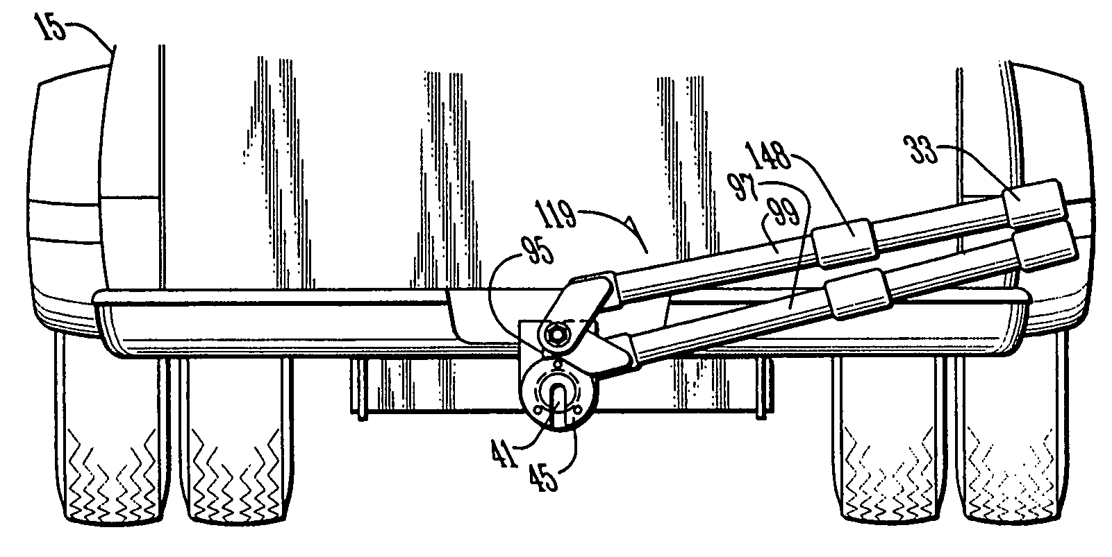
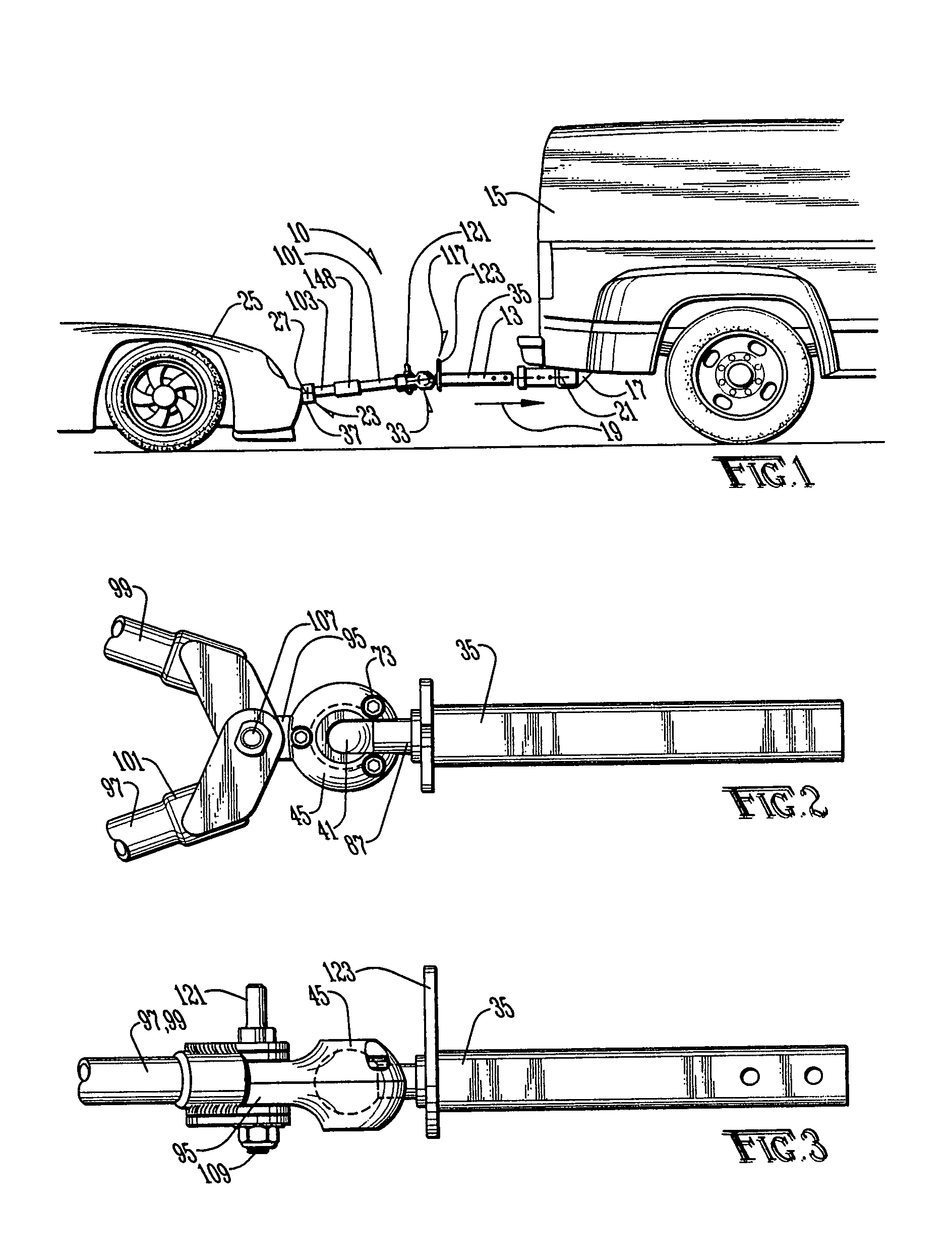
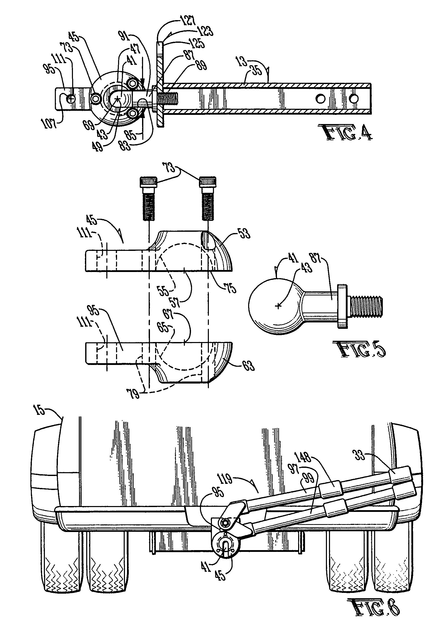
[0071]In an application of embodiment 10 of the present invention, the hitching mechanism 35 is inserted and secured in the conventional receiver hitch 17 of the towing vehicle 15. If the tow bar 10 has been previously secured to the towing vehicle 15 and is in the stowed configuration 119, then the tow bar arms 97, 99 are grasped and maneuvered to disengage the latching mechanism 117, to rotate the body member 45 about the ball member 41 to thereby displace the towbar arms 97, 99 rearwardly toward the towed vehicle 25, and to secure the towed vehicle connection mechanism 23 to the towed vehicle 25. Of course, an application of the tow bar 10 would also involve the proper use of safety chains, electrical hookups, etc., as commonly known in the art.

[0072]Conversely, if the towed vehicle 25 is to be temporarily disconnected from the towing vehicle 15, the towed vehicle connection mechanism 23 is disconnected from the towed vehicle 25; the tow bar arms 97, 99 are used to rotate the bod...

embodiment 150

[0074]The modified embodiment 150 includes a towing vehicle connection mechanism 153 for connecting the tow bar 150 to a towing vehicle 15, the towing vehicle connection mechanism 153, upon insertion and securement in the conventional receiver hitch 17 of the towing vehicle 15 operatively defining a fore-to-aft towing vehicle axis 155 that is fixed relative to the towing vehicle 15 and to the towing vehicle connection mechanism 153; a towed vehicle connection mechanism 157 for connecting the tow bar 150 to the towed vehicle 25, the towed vehicle connection mechanism 157 operatively defining a horizontal transversely-oriented towed vehicle axis 159 that is fixed relative to the towed vehicle 25 and to the towed vehicle connection mechanism 157; and an interconnecting mechanism 161 connecting the towing vehicle connection mechanism 153 to the towed vehicle connection mechanism 157.

[0075]The modified embodiment 150 of the present invention includes a body member 163 having a first body...


PUM


Abstract

A tow bar for connecting a towed vehicle to a towing vehicle, the tow bar comprising a towing vehicle connection mechanism connected to the towing vehicle; a towed vehicle connection mechanism connected to the towed vehicle; and an interconnecting mechanism connecting the towing vehicle connection mechanism to the towed vehicle connection mechanism. The interconnecting mechanism defines an interconnection central point and an interconnection vertical axis spaced rearwardly from the interconnection central point. The interconnecting mechanism is structured to accommodate substantially all pitch and roll movements between the towing and towed vehicles at and about the interconnection central point, and to accommodate substantially all yaw movements between the towing and towed vehicles at and about the interconnection vertical axis.

Description

CROSS REFERENCE TO RELATED APPLICATIONS[0001]This application is a divisional application of U.S. application Ser. No. 10 / 840,033 filed May 7, 2004, now U.S. Pat. No. 6,991,247. U.S. application Ser. No. 10 / 910,543 filed Aug. 4, 2004, now U.S. Pat. No. 7,032,919 is a continuation-in-part application of U.S. application Ser. No. 10 / 840,033 filed May 7, 2004, now U.S. Pat. No. 6,991,247.BACKGROUND OF THE INVENTION[0002]1. Field of the Invention[0003]The present invention is related to accessories for vehicles and, more specifically without limitation, to an apparatus for towing a vehicle behind another vehicle.[0004]2. Discussion of the Related Art[0005]There is an ever-increasing need to be able to tow a driverless vehicle behind another vehicle. One common situation where this need arises occurs for persons traveling in a motorhome. Most motorhomes are too large to conveniently visit many sites of interest near an overnight stop-over. As a result, many motorhome users tow a small au...

Claims


Application Information

Patent Timeline
Patent Type & Authority Patents(United States)
IPC IPC(8): B60D1/54
CPCB60D1/00B60D1/065B60D1/167B60D1/54
Inventor HAHNE, MERTONPENLERICK, MARKCRIPPEN, ANTHONY
Owner AUTOMATIC EQUIP MFG
Why Eureka
Try Eureka