Backlight device

a backlight device and chroma uniform technology, applied in indirect heat exchangers, lighting and heating apparatuses, instruments, etc., can solve the problems of affecting the display quality, affecting the service life of cold cathode fluorescent lamps and other components, impaired brightness and chroma uniformity of backlight devices, etc., to improve brightness and chroma uniformity, improve brightness and brightness of regions, and eliminate dark regions

Inactive Publication Date: 2008-11-04
HON HAI PRECISION IND CO LTD
View PDF10 Cites 4 Cited by
  • Summary
  • Abstract
  • Description
  • Claims
  • Application Information

AI Technical Summary

Benefits of technology

[0013]Compared with conventional backlight device, the present backlight device has the following advantages. Because the light source module includes at least one cold cathode fluorescent lamp, and the cold cathode fluorescent lamp includes at least two parallel linear portions and at least one intermediate portion interconnected to the parallel linear portions, the intermediate portion can enhance brightness of the regions between the two neighboring parallel linear portions and eliminate dark regions, and improve brightness and chroma uniformity. Further, the backlight device includes a cooling module, the heat generated by the light source module can be effectively dissipated. The temperature of the cold cathode fluorescent lamp is lowered, and so maintained within a safety range. Thus, the light emitting capability of the cold cathode fluorescent can be fully exploited. The brightness of the light source module is improved, and the utilization efficiency of light thereof is accordingly increased.

Problems solved by technology

Therefore, brightness and chroma uniformity of the backlight device 10 are impaired.
The high temperature will adversely influence the displaying quality and reduce the service life of the cold cathode fluorescent lamps and other components adjacent to the lamps.

Method used


Image

  • Backlight device
  • Backlight device
  • Backlight device

Examples


Embodiment Construction

[0025]Reference will now be made to the drawings to describe preferred embodiments of the present backlight device, in detail.

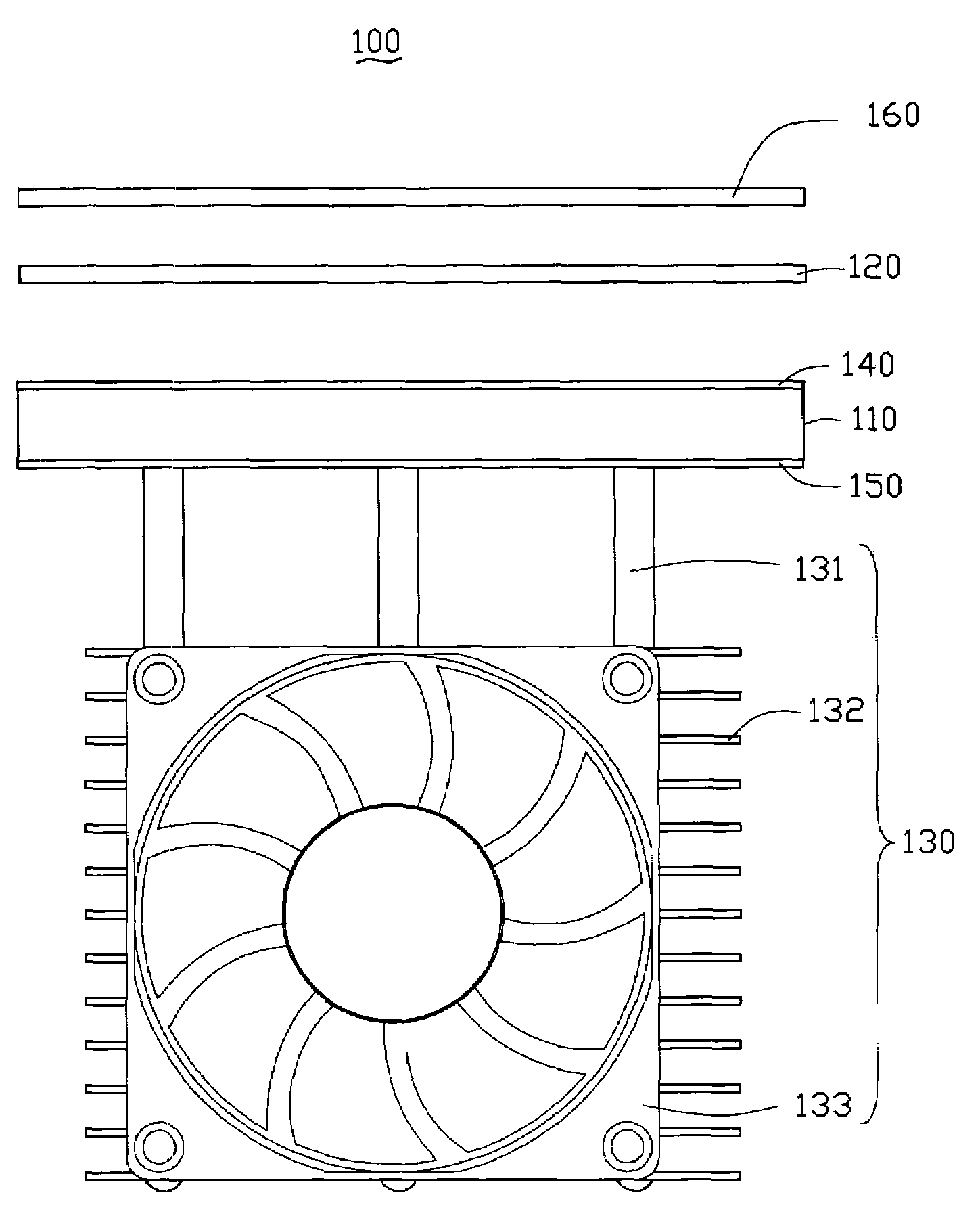
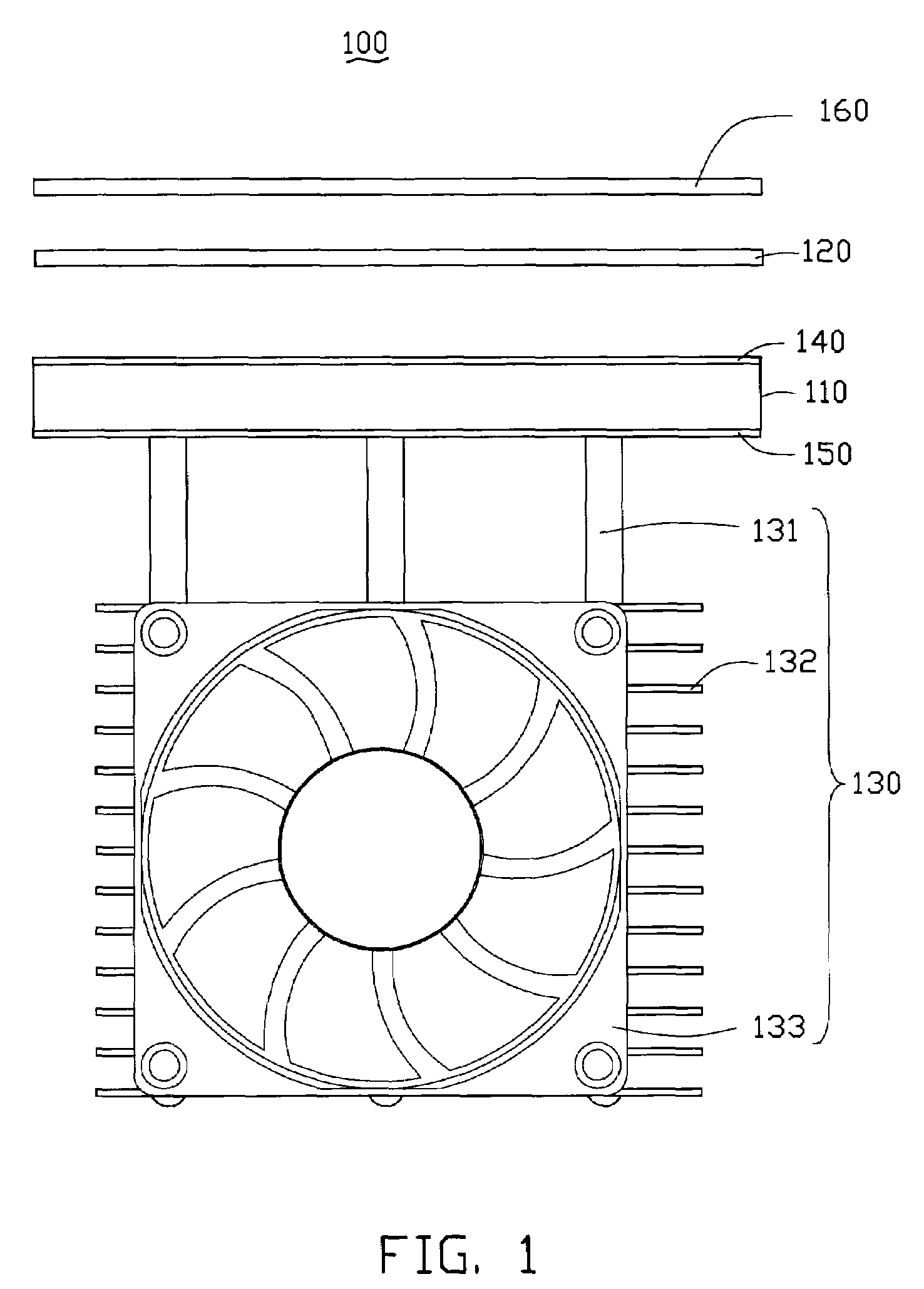
[0026]Referring to FIGS. 1 to 3, a backlight device 100, in accordance with a first preferred embodiment, is shown. The backlight device 100 is a direct type backlight device and includes a reflection plate 110 having a reflective surface and an opposite heat dissipating surface, a light source module 120 disposed adjacent to the reflective surface of the reflection plate 110, and a cooling module 130 attached on the heat dissipating surface of the reflection plate 110.

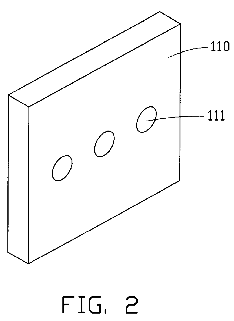
[0027]The reflection plate 110 can be made from a thermally conductive material with high heat conducting property, such as Copper (Cu) or Aluminum (Al), preferably Cu. As shown in FIG. 2, a number of holes 111 are uniformly defined on the heat dissipating surface of the reflection plate 110. The holes 111 extend in a direction perpendicular to a main plane of the reflection plate 110. A reflec...


PUM


Abstract

A backlight device (100) includes a reflection plate (110) having a reflective surface and a heat dissipating surface, and a light source module (120) disposed adjacent to the reflective surface of the reflection plate; the light source module comprising at least one cold cathode fluorescent lamp, and the cold cathode fluorescent lamp comprising at least two parallel linear portions (122) and at least one intermediate portion (121) interconnected to the at least two linear portions. The backlight device further includes a cooling module (130). The cooling module is attached on the heat dissipating surface of the reflection plate. The present backlight device can improve brightness and chroma uniformity. And the brightness of the light source module is improved, and the utilization efficiency of light thereof is also increased, accordingly.

Description

FIELD OF THE INVENTION[0001]The present invention relates to backlight devices and, more particularly, to a direct type backlight device with a high displaying quality and a self-cooling function.DESCRIPTION OF RELATED ART[0002]Nowadays, liquid crystal materials are widely utilized in various liquid crystal displays having different sizes for different applications, such as TVs, liquid crystal projectors, mobile telephones, personal digital assistants (PDA), etc. Because liquid crystal itself cannot emit light, light sources must be utilized to illuminate liquid crystal for image display. The light sources are called backlight sources since they are usually configured behind liquid crystal panels. A combination of all components behind the liquid crystal panels, including the light sources, is generally referred to as a backlight module. Usually, backlight modules can be classified into edge lighting backlight devices and direct type backlight devices.[0003]Referring to FIG. 8, a co...

Claims


Application Information

Patent Timeline
Patent Type & Authority Patents(United States)
IPC IPC(8): F21V29/02
CPCF21V29/30F28D15/0275G02F1/133604G02F2001/133628F21V29/006F21V29/71F21V29/51F21V29/67F21V29/89G02F1/133628
Inventor CHEN, GA-LANE
Owner HON HAI PRECISION IND CO LTD
Why Eureka
Try Eureka